
Page 261 - Machinery Component Maintenance
P. 261
Balancing of Machinery Components 243
Principal Unbalance
-----
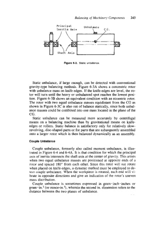
Figure 6-3. Static unbalance.
Static unbalance, if large enough, can be detected with conventional
gravity-type balancing methods. Figure 6-3A shows a concentric rotor
with unbalance mass on knife edges. If the knife-edges are level, the ro-
tor will turn until the heavy or unbalanced spot reaches the lowest posi-
tion. Figure 6-3B shows an equivalent condition with an eccentric rotor.
The rotor with two equal unbalance masses equidistant from the CG as
shown in Figure 6-3C is also out of balance statically, since both unbal-
ance masses could be combined into one mass located in the plane of the
CG .
Static unbalance can be measured more accurately by centrifugal
means on a balancing machine than by gravitational means on knife-
edges or rollers. Static balance is satisfactory only for relatively slow-
revolving, disc-shaped parts or for parts that are subsequently assembled
onto a larger rotor which is then balanced dynamically as an assembly.
Couple Unbalance
Couple unbalance, formerly also called moment unbalance, is illus-
trated in Figure 6-4 and 6-4A. It is that condition for which the principal
axis of inertia intersects the shaft axis at the center of gravity. This arises
when two equal unbalance masses are positioned at opposite ends of a
rotor and spaced 180" from each other. Since this rotor will not rotate
when placed on knife-edges, a dynamic method must be employed to de-
tect couple unbalance. When the workpiece is rotated, each end will vi-
brate in opposite directions and give an indication of the rotor's uneven
mass distribution.
Couple unbalance is sometimes expressed in gram inch * inches or
gram-in.2 (or ounce-in.2), wherein the second in. dimension refers to the
distance between the two planes of unbalance.