
Page 265 - Machinery Component Maintenance
P. 265
Balancing of Machinery Components 247
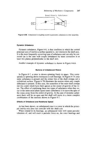
Quasi-Static Unbalance
Figure 6-58. Unbalance in coupling causes quasi-static unbalance in rotor assembly.
Dynamic Unbalance
Dynamic unbalance, Figure 6-6, is that condition in which the central
principal axis of inertia is neither parallel to, nor intersects the shaft axis.
It is the most frequently occurring type of unbalance and can only be cor-
rected (as is the case with couple unbalance) by mass correction in at
least two planes perpendicular to the shaft axis.
Another example of dynamic unbalance is shown in Figure 6-6A.
Motions of Unbalanced Rotors
In Figure 6-7, a rotor is shown spinning freely in space. This corre-
sponds to spinning above resonance in soft bearings. In Figure 6-7A only
static unbalance is present and the center line of the shaft sweeps out a
cylindrical surface. Figure 6-7B illustrates the motion when only couple
unbalance is present. In this case, the centerline of the rotor shaft sweeps
out two cones which have their apexes at the center-of-gravity of the ro-
tor. The effect of combining these two types of unbalance when they oc-
cur in the same axial plane (quasi-static unbalance) is to move the apex of
the cones away from the center-of-gravity. In the case of dynamic unbal-
ance there will be no apex and the shaft will move in a more complex
combination of the motions shown in Figure 6-7.
Effects of Unbalance and Rotational Speed
As has been shown, an unbalanced rotor is a rotor in which the princi-
pal inertia axis does not coincide with the shaft axis.
When rotated in its bearings, an unbalanced rotor will cause periodic
vibration of, and will exert a periodic force on, the rotor bearings and