
Page 260 - Machinery Component Maintenance
P. 260
242 Machinery Component Maintenance and Repair
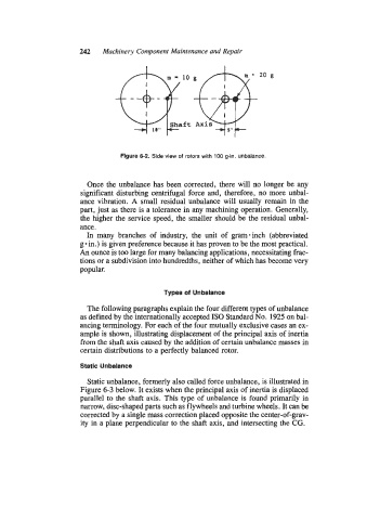
Figure 6-2. Side view of rotors with 100 g-in. unbalance.
Once the unbalance has been corrected, there will no longer be any
significant disturbing centrifugal force and, therefore, no more unbal-
ance vibration. A small residual unbalance will usually remain in the
part, just as there is a tolerance in any machining operation. Generally,
the higher the service speed, the smaller should be the residual unbal-
ance.
In many branches of industry, the unit of gram-inch (abbreviated
g in.) is given preference because it has proven to be the most practical.
An ounce is too large for many balancing applications, necessitating frac-
tions or a subdivision into hundredths, neither of which has become very
popular.
Types of Unbalance
The following paragraphs explain the four different types of unbalance
as defined by the internationally accepted IS0 Standard No. 1925 on bal-
ancing terminology. For each of the four mutually exclusive cases an ex-
ample is shown, illustrating displacement of the principal axis of inertia
from the shaft axis caused by the addition of certain unbalance masses in
certain distributions to a perfectly balanced rotor.
Static Unbalance
Static unbalance, formerly also called force unbalance, is illustrated in
Figure 6-3 below. It exists when the principal axis of inertia is displaced
parallel to the shaft axis. This type of unbalance is found primarily in
narrow, disc-shaped parts such as flywheels and turbine wheels. It can be
corrected by a single mass correction placed opposite the center-of-grav-
ity in a plane perpendicular to the shaft axis, and intersecting the CG.