
Page 346 - Machinery Component Maintenance
P. 346
328 Machinery Component Maintenance and Repair
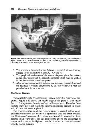
Figure 6-49. Field balancing of a bunching machine. Using the balancing and vibration an-
alyzer “VIBROTEST,” the unbalance vibration in the four bearing planes is measured suc-
cessively in terms of amount and angular position.
3. The procedure described under 2 above is repeated with calibrating
masses in the correction planes A2, A3 and A4.
4. The graphical evaluation of the vector diagram gives the amount
and angular position of the correction masses which must be applied
in the four chosen correction planes.
5. After unbalance correction a check measurement is carried out and
the residual vibrations determined by this are compared with the
permissible tolerance values.
The Vector Diagram
The results from the five measuring runs are entered in four vector dia-
grams. Figure 6-50 shows the vector diagram for plane l. The vector
(a) . . . (b) represents the effect of the calibration mass. The other three
vectors show the effect which the calibration masses applied in planes
A1 , A3, and A4 exert in plane 1.
The graphic evaluation of the vector diagram is carried out by an ap-
proximation method. By means of a systematic trial and error process,
combinations of masses are determined which result in a reduction of un-
balance in all four planes. For this purpose the effects and influences of
the correction masses in all planes must be taken into account and entered
into the vector diagram.