
Page 341 - Machinery Component Maintenance
P. 341
Balancing of Machinery Components 323
\-
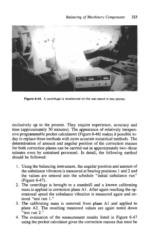
Figure 6-44. A centrifuge is rebalanced on the test stand in two planes.
exclusively up to the present. They require experience, accuracy and
time (approximately 30 minutes). The appearance of relatively inexpen-
sive programmable pocket calculators (Figure 6-46) makes it possible to-
day to replace these methods with more accurate numerical methods. The
determination of amount and angular position of the correction masses
for both correction planes can be carried out in approximately two-three
minutes even by untrained personnel. In detail, the following method
should be followed:
1. Using the balancing instrument, the angular position and amount of
the unbalance vibration is measured at bearing positions 1 and 2 and
the values are entered into the schedule “initial unbalance run”
(Figure 6-47).
2. The centrifuge is brought to a standstill and a known calibrating
mass is applied in correction plane A 1. After again reaching the op-
erational speed the unbalance vibration is measured again and en-
tered “test run 1.”
3. The calibrating mass is removed from plane A1 and applied to
plane A2. The resulting measured values are again noted down
“test run 2.”
4. The evaluation of the measurement results listed in Figure 6-47
using the pocket calculator gives the correction masses that must be