
Page 340 - Machinery Component Maintenance
P. 340
322 Machinery Component Maintenance and Repair
the permissible values. The need to correct this may arise when test run-
ning a new centrifuge and after repair and overhaul of older installations.
Solution: Field Balancing in Two Planes
Disassembly, additional machining, excess costs, and user complaints
may be avoided by rebalancing on the test stand (Figure 6-44) or at the
final point of installation. Because of the geometry of the centrifuge
drum, field balancing in two planes is almost always necessary in order
to improve the unbalance condition effectively. For this purpose the un-
balance vibration is measured at two bearing positions as shown in Fig-
ure 6-45 and the unbalance determined in this way is corrected in two
radial planes A1 and A2.
Measurement is carried out with a portable electronic balancing instru-
ment that indicates the amount and angular position of the unbalance vi-
bration for both measuring positions with frequency selectivity. For the
evaluation of measured results, graphical methods have been used almost
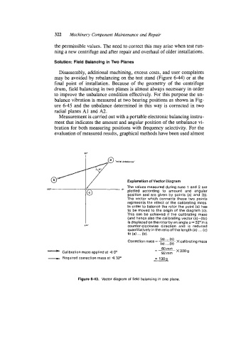
/ Explanation of Vector Diagram
8 0. The values measured during runs 1 and 2 are
plotted according to amount and angular
position and are given by points (a) and (b).
The vector which connects these two points
represents the effect of the calibrating mass.
In order to balance the rotor the point (a) has
to be moved to the origin of the diagram (c).
This can be achieved if the calibrating mass
(and hence also the calibrating vector (a) -(b))
is displaced on the rotor bv an anale a- 32Oin a
270- counter-clockwise direction ani is reduced
quantitatively in the ratio of the length (a). . . (c)
to (a) ... (b).
Correction mass = - (a).'.(c) Xcalibrating mass
(a). . . (b)
-
-
- Calibration mass applied at 4 Oo 60mrn x200g
92 mrn
- Required correction mass at 4 32' = 1309
Figure 6-43. Vector diagram of field balancing in one plane.