
Page 345 - Machinery Component Maintenance
P. 345
Balancing of Machinery Components 327
Solution: Field Balancing in Several Planes
The unbalance and vibrational behavior of multiple bearing rotor sys-
tems may be improved in a systematic manner by multi-plane balancing
in the assembled state (Figure 648). For unbalance correction, there
must be a correction plane for every bearing position on the rotor. For
example, the four-bearing rotor shown in Figure 648 requires four cor-
rection planes.
The electronic balancing instrument for this task is identical to the in-
struments used for single and two plane balancing. It is resting on top of
the bunching machine being shown, during field balancing, in Figure
6-49. The balancing process only differs in the number of calibrating
runs and the way the measured results are evaluated:
1. Using the portable balancing instrument the phase position and
amount of the unbalance vibrations is measured at the four bearing
positions of the stranding machine. These “initial unbalance val-
ues” are entered on four vector diagrams similar to that in Figure 6-
50.
2. The stranding machine is switched off and a known calibrating
mass is applied in the correction plane A1 (Figure 6-48). After run-
ning up to the operational speed the unbalance values are again
measured at the four bearing positions. These values are also en-
tered in the vector diagram.
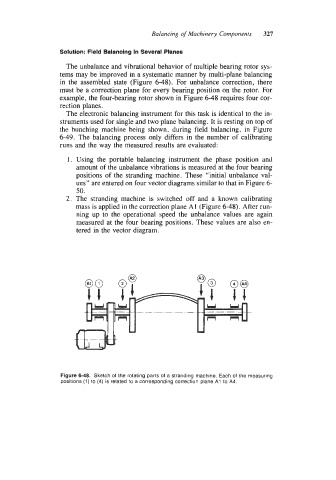
Figure 6-48. Sketch of the rotating parts of a stranding machine. Each of the measuring
positions (1) to (4) is related to a corresponding correction plane AI to A4.