
Page 339 - Machinery Component Maintenance
P. 339
Balancing of Machinery Components 321
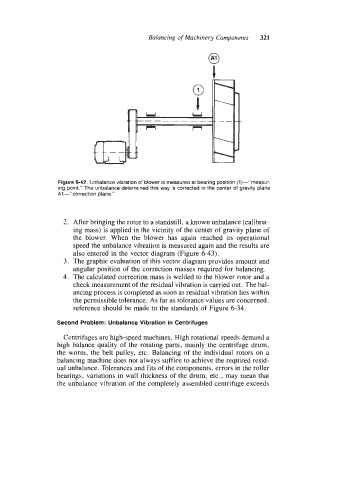
Figure 6-42. Unbalance vibration of blower is measurea at bearing position (1)-”rneasur-
ing point.” The unbalance determined this way is corrected in the center of gravity plane
A1 -“correction plane.”
2. After bringing the rotor to a standstill, a known unbalance (calibrat-
ing mass) is applied in the vicinity of the center of gravity plane of
the blower. When the blower has again reached its operational
speed the unbalance vibration is measured again and the results are
also entered in the vector diagram (Figure 6-43).
3. The graphic evaluation of this vector diagram provides amount and
angular position of the correction masses required for balancing.
4. The calculated correction mass is welded to the blower rotor and a
check measurement of the residual vibration is carried out. The bal-
ancing process is completed as soon as residual vibration lies within
the permissible tolerance. As far as tolerance values are concerned.
reference should be made to the standards of Figure 6-34.
Second Problem: Unbalance Vibration in Centrifuges
Centrifuges are high-speed machines. High rotational speeds demand a
high balance quality of the rotating parts. mainly the centrifuge drum,
the worm, the belt pulley, etc. Balancing of the individual rotors on a
balancing machine does not always suffice to achieve the required resid-
ual unbalance. Tolcrances and fits of the components, errors in the roller
bearings, variations in wall thickness of the drum, etc., may mean that
the unbalance vibration of the completely assembled centrifuge exceeds