
Page 334 - Machinery Component Maintenance
P. 334
316 Machinery Component Maintenance and Repair
Multiple Machine Control and Programs
Different computers may be used depending on the application. They
may be mounted in the balancing machine’s instrumentation console, or
in a central electronic data processing room. A computer may control one
balancing machine, or a series of machines.
Basic computer programs are available for single and two plane bal-
ancing, field balancing, and flexible rotor balancing. Software libraries
for optional subroutines are continually growing.
Of course, the user may modify the available programs to his particu-
lar requirements, write his own programs, or have them written for him.
Thus, the potential applications of the computerized hard-bearing balanc-
ing machines are unlimited.
Balancing Program No. 002
Rotor Data
ROTOR NAHE I SAMPLE
ROTOR BALANCING SPEED 750 RPH
INSTRUMENT SPEED RANGE 396-1000 RPM
BALANCING MODE DYNAMIC
LEFT PLANE TO LEFT SUPPORT DISTANCE ‘A’ = 4.10 INCHES
LEFT PLANE TO RIGHT PLANE DISTANCE ‘E’ 10.00 INCHES
RIGHT PLANE TO RIGHT SUPPORT DISTANCE ‘C‘ - 4.10 INCHES
CORRECTION RADIUS, LEFT PLANE ‘Rl’ - 3.50 INCNES
CORRECTION RADIUS, RIGHT PLANE ’R2’ = 3.50 INCHES
BALANCING TOLERANCE, LEFT PLANE = 20.00 GRAM-INCHES
BALANCING TOLERANCE. RIGHT PLANE - 20.0~ GRAM-INCHES
ROTOR S/N 123AIlC
Unbalance Data
RUN LEFT PLANE RIGHT PLANE
ROTOR S/N 123ABC IS BALANCED UITHIN TOLERANCES
RESIDUAL UNBALANCE DATA:
PLANE 1 AMOUNT = 2.9e19 GRRH-INCNES
PLANE i ANGLE = 186 DEGREES
PLANE 2 AMOUNT = 1.6717 GRAIl-INCNES
PLANE 2 ANGLE - 277 DEGREES
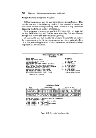
Figure 6-40. Printout of unbalance data.