
Page 329 - Machinery Component Maintenance
P. 329
&lancing of Machinery Components 31 1
Index-Balancing Procedure
A procedure of repetitively balancing and indexing (by 1 SO0) one com-
ponent against another leads to diminishing residual unbalance in both,
until eventually one component can be indexed against the other without
a significant change in residual unbalance. Index-balancing may be used
to eliminate the unbalance errors in an end-drive adapter, for biasing an
arbor or for improving the rcsidual unbalance in a rotor mounted on an
arbor.
If the procedure is used for a single-plane application (e.g., an end-
drive adapter), one half of the residual unbalance (after the first index-
ing) is corrected in the adapter, the other half in the rotor. The cycle may
have to be repeated once or twice until a satisfactory residual unbalance
is reached.
Care should be taken that after each indexing step, set screws are tight-
ened with the same torque and in the same sequence. The procedure does
not work well unless the position of the indexed component is precisely
repeatable.
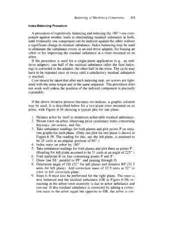
If the above iterative process becomes too tedious, a graphic solution
may be used. It is described below for a two-plane rotor mounted on an
arbor, with Figure 6-38 showing a typical plot for one plane.
1. Balance arbor by itself to minimum achievable residual unbalance.
2. Mount rotor on arbor, observing prior cautionary notes concerning
keyways, set screws, and fits.
3. Take unbalance readings for both planes and plot points P on sepa-
rate graphs for each plane. (Only one plot for one plane is shown in
Figure 6-38. The reading for this, say the left plane, is assumed to
be 35 units at an angular position of 60".)
4. Index rotor on arbor by 180".
5. Take unbalance readings for both planes and plot them as points P ' .
(Reading for left plane assumed to be 3 1 units at an angle of 225 O .)
6. Find midpoint R on line connecting points P and P' .
7. Draw line SS' parallel to PP' and passing through 0.
8. Determine angle of OS (52" for left plane) and distance RP (32.5
units for left plane). Add correction mass of 32.5 units at 52" to
rotor in left correction plane.
9. Steps 6-8 must also be performed for the right plane. The rotor is
now balanced and the residual unbalance (OR in Figure 6-38) re-
maining in the arborhotor assembly is due to arbor unbalance and
run-out. If this residual unbalance is corrected by adding a correc-
tion mass to the arbor equal but opposite to OR, the arbor is cor-