
Page 327 - Machinery Component Maintenance
P. 327
&lancing of Machinery Components 309
U,,, test described earlier may be used to determine whether the speci-
fied tolerance has been reached. The test should be carried out separately
for each correction plane, and a test mass equivalent to 10 times the toler-
ance should be used for each plane.
Balance Errors Due to Drive Elements
During balancing in general, and during the check on tolerance com-
pliance in particular, significant errors can be caused by the driving ele-
ments (for example, driving adapter and universal-joint drive shaft).
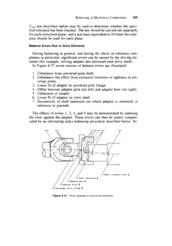
In Figure 6-3j seven sources of balance errors &e illustrated:
1. Unbalance from universal-joint shaft.
2. Unbalance-like effect from excessive looseness or tightness in uni-
versal joints.
3. Loose fit of adapter in universal-joint flange.
4. Offset between adapter pilot (on left) and adapter bore (on right).
5. Unbalance of adapter.
6. Loose fit of adapter on rotor shaft.
7. Eccentricity of shaft extension (on which adapter is mounted) in
reference to journals.
The effects of errors 1, 3, 4, and 5 may be demonstrated by indexing
the rotor against the adapter. These errors can then be jointly compen-
sated by an alternating index-balancing procedure described below. Er-
Figure 6-37. Error sources in end-drive elements