
Page 89 - Macromolecular Crystallography
P. 89
78 MACROMOLECULAR CRYS TALLOGRAPHY
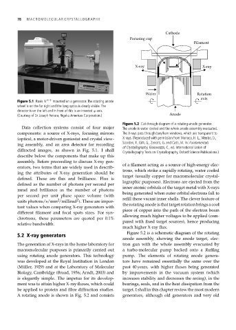
Cathode
Focusing cup
Filament
X-ray X-ray
Water Rotation
axis
Figure 5.1 Raxis IV ++ mounted on a generator. The rotating anode
wheel is on the far right and the long optics is clearly visible. The
detector is on the left and in front of this is an inverted ϕ-axis.
(Courtesy of Dr Joseph Ferrara, Rigaku Americas Corporation.) Anode
Figure 5.2 Cut-through diagram of a rotating-anode generator.
Data collection systems consist of four major The anode is water cooled and the whole anode assembly evacuated.
components: a source of X-rays, focusing mirrors The X-rays pass through beryllium windows, which are transparent to
(optics), a motor-driven goniostat and crystal view- X-rays. (Reproduced with permission from Monaco, H. L.,Viterbo, D.,
Scordari, F., Gilli, G., Zanotti, G. and Catti, M. In: Fundamentals
ing assembly, and an area detector for recording
of Crystallography, Giacovazzo, C., ed. International Union of
diffracted images, as shown in Fig. 5.1. I shall
Crystallography Texts on Crystallography, Oxford Science Publications.)
describe below the components that make up this
assembly. Before proceeding to discuss X-ray gen-
of a filament acting as a source of high-energy elec-
erators, two terms that are widely used in describ-
trons, which strike a rapidly rotating, water cooled
ing the attributes of X-ray generation should be
target (usually copper for macromolecular crystal-
defined. These are flux and brilliance. Flux is
lographic purposes). Electrons are ejected from the
defined as the number of photons per second per
inner atomic orbitals of the target metal with X-rays
mrad and brilliance as the number of photons
being generated when outer orbital electrons fall to
per second per unit phase space volume (with
2
2
units photons/s/mm /millirad ). These are impor- refill these vacant inner shells. The clever feature of
the rotating anode is that target rotation brings a cool
tant values when comparing X-ray generators with
piece of copper into the path of the electron beam
different filament and focal spots sizes. For syn-
allowing much higher voltages to be applied (com-
chrotrons, these parameters are quoted per 0.1%
pared with fixed target sources), hence producing
relative bandwidth.
much higher X-ray flux.
Figure 5.2 is a schematic diagram of the rotating
5.2 X-ray generators
anode assembly, showing the anode target, elec-
The generation of X-rays in the home laboratory for tron gun with the whole assembly evacuated by
macromolecular purposes is primarily carried out a turbo-molecular pump backed onto a Ruffing
using rotating anode generators. This technology pump. The elements of rotating anode genera-
was developed at the Royal Institution in London tors have remained essentially the same over the
(Müller, 1929) and at the Laboratory of Molecular past 40 years, with higher fluxes being generated
Biology, Cambridge (Broad, 1956; Arndt, 2003) and by improvements in the vacuum system (which
is elegantly simple. The impetus for its develop- increases stability and decreases the arcing), in the
ment was to attain higher X-ray fluxes, which could bearings, seals, and in the heat dissipation from the
be applied to protein and fibre diffraction studies. target. I shall in this chapter review the most modern
A rotating anode is shown in Fig. 5.2 and consists generators, although old generators and very old