
Page 100 - Making PIC Microcontroller Instruments and Controllers
P. 100
90 flMEnS Al{t COU TERS
Bit 3 =1 Enables an interupt if any of the PORTB pins are programmed as inputs
and change state.
Bit 2 Is the Intempt flag for Time .
Bit I Is the Intenupt flag for all intemal intertupts.
Bit 0 Is the Intefiupt flag for pins 87 to B4 if they change state.
Note that Bit 2 is set clear when we start and will be sel to I when the iirst interupt
takes place.It has to be re-cleared within the interrupt service routine thercafter. (This
is usually at the end ofthe routine, but not necessarily so.)
A TIMERo CLOCKT FROM A PROGRAIII BY IUICHOENGINEERIiIG
LABS lot{ THETR WEB SrrE)
The following program, written by microEngineering Labs and prcvided by them as a
part of the information on their Web site, demonstrates the use of intemrpts to create a
reasonably accurate clock lbat uses the LCD display to show the time in hou$, minutes,
LCD CLOCK PROGNA USING OII INIERRUPT
This program uses TMRo and prescalar. Watchdog timer should be set to OFF at pro-
gram time, and Nap and Sleep should not be used.
Buttons may be used to set hous and minutes.
In Program 6.3, the CLEAR and OSC commands are not used, but we will ahvays
use them in our programs.
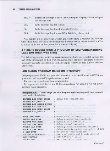
Labs program (Hou|s, seconds,
iili!!ii.!i!t!i!l:l Timero usage per mlcroEngineering
and minules digital clock)
DEFINE I,CD_DRIG PORTD denne LCD connections
DEFINE I,CD_DBIT 4
DEFINE I,CD_RSREG PORTE
DEFINE IJCD_RSBI' O
DEFINE IJCD_EREG POREE
DEFINE LCD_EBIT 1
IIOUR VAR BYTE define hour wariable
DEOUR VAR BYTE define display hour variable
IIINUTE VlR BYTE denne ninute variable
SECOND VAR BYTE denne second variable
ETCRS VAR BYTE deine pieces of seconds variable
UPDAIE 1IAR BYTE define variable to indicare update of LcD
I VAR BYTE de bounce loop wariabte
A.DcoNl = %00000111 parls of PORTA and E nade digrital
LOII PORTE.2 LCD R/w Lov = write
PAOSE 100 wait for LCD to startup