
Page 99 - Making PIC Microcontroller Instruments and Controllers
P. 99
TIMERO A9
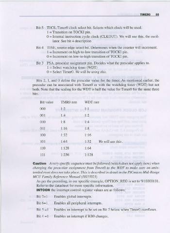
Bit 5 T0CS, Timer0 clock select bit. Selects which clock wjll be used.
I = Transition on TOCKI pin.
0 = Internal instruction cycle clock (CLKOUT). We will use this, thc oscil-
lator- See bit 4 description
Bit 4 TOSE, source edge select bit. Detemines when the counter will increment.
I = Increment on high-tolow transitior of TOCKI pin.
0 = lncrement on low-to-high transition of TOCKI pin.
Bir 3 PSA, prescalar assignment piII. Decides what the presca]ar applies to-
I = Select watchdoC timer (WDT)
0 = SelectTimero. We 'rill be using this.
Bits 2, 1, and 0 define the prescalar value for the timer. As mentioned edrlier, fie
prescalar can be associated with Timero or with the watchdog timer (WDT) but not
both. Note that the scaliflg for the wDT is half the va]ue for Timero for the same three
Bit vaiue TMR0 rate WDT late
000 ltz lrl
001 l:4 1:2
010 1:8 l:4
011 1:16 1:8
100 t:32 l: 6
1
l0l l:64 l:32 We will use this.
ll0 1:128 1:64
111 11256 1:128
Caulion A rery specifc sequence nust he followe.l (which does not apply here ) whetl
changins the prescalar assignment fron Tiner, to the WDT to make sure an unin-
tended reset does not take place.This is described in detdil in the PICmictu Mid-Ranqe
MCU Foni\, Refercnce Manual (DS33023)
As per the preceding, in our specific example, OPTION REG is set to 7.10000101.
Refer to the datasheet for more specific information.
ll{TCOl{ the intemrpt control register values are as follows:
BitT=l Enables global intenupts.
Bit 6=l Lnable' all pcnphcrdl inleruplr.
Bit5=I Enables an interrupt to be setonBit2 below when Time overflows.
Bit 4 = I Enables an inte[upt if RBO changes.