
Page 98 - Making PIC Microcontroller Instruments and Controllers
P. 98
ee fl ERs at{D cout{TEns
and
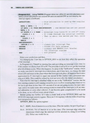
a:!!4ff!!il{l.g* UsinsTlMERo (Program blinks iwo LEDS [D1 and D0]allernalelv
blinks a thrrd LED [D2]for one second ON and one s€cond OFF as conlrolled bythe
inlerrupl signal) (Contlnued)
IMIROUTINE: ; bhis infornation ls used bv Lhe conpiler
; odLv'
B E T A = B E T A + 1
IF BETA < 51 TIlriN ENDMITERRUPT ; one second has noL vet passed
BEEA = 0 ;
tF PoRTD.3 = I IHEN ; inlerrupi loop lurns D3 on and off everv
PORTD.3 = 0 ; 61 tines through the inter:rupt routine.
EISE ; ThaL is about one second per fulL cvcle
PORED.3 = 1
ENDIF
t
ETIDTNIIERRUPT
tN!coN.2 = 0 ; clears the inlerrupt flaq,
REAU!@ ; -esua h6 ma:- o oo dn
ENAS!,E ; DISABLE ANd ENABLE NUST bTACKCT
; the interrup! routine
END ; end prograrn
Make your predictions and then...
Try changing the 3 low bits in OPTION-REG to see how they affect tbe operntion
of the interruPt.
In Program 6.2, Timer0 is running free and providing an interrupt every time its
8 bil counter ovedows from FF to 00. The prescalar is set to 64 so we get the interrupt
after 64 of these cycles. When this happens, we jump to the "lntRoutlne" routine, where
we make sure that 61 intetrupts have taken place, and if they have, we change thc sfate
of an LED and retum to the place where the interupl took place. (It happens that it takes
approximately 61 inteffupts to equal one second in this routine with a processor run
ning at 4 MHz. This could be relined by trial ard error after the initial calculation )
Note that the interrupt is disabled while we are in the "IntRoutine" routine, but the
iree running counter is still running towad its next overflow meaning that whatever we
alo has to get done in less than 1/61 seconds if we are not going to miss the next inter-
rupt, unless we make some other arrangements to count all the interupts (with an inler-
nal subroutine or some other scheme). It can become quite complicated if a lot needs
to be done, so we will not worry about it here
Before going any further, let's take a closer look at the OPTION-REG and the
INTCON (intenupt control) register. These are 8_bit registers witb the 8 bits ofeach reg-
ister assigned as follows:
OPTION-REG the option register:
Bit 7 RBPU. Nol ofinterest to us at this time. (This bit enables the po( B pull ups-)
Bit 6 INTEDG. Not of interest to us at this time. (The intefiupt edge select bil
detemines which edge the interupt will be selected on, rising [1] or falling
[0]). Either one works for us.