
Page 109 - Making PIC Microcontroller Instruments and Controllers
P. 109
tllf,EFlr THE SEGo D TIIER 90
fT fT T-trTI
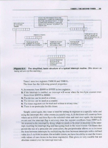
The simpllfied, basic structure ol a lypical interupt routine. (Biis shown as
ffiElll
being sel are notthe realbits.)
Timerl uses two registers TMR1H andTMRIL.
The fimer has the following general prope$ies:
l. Inqements from $0000 to $FFFF in two registers.
2. If the interupt is enabled, an interrupt will occur when the two byte counter over-
flows tuom $FFFF to $0000.
3. The device can be used as a timer.
4. The device can be used as a counter.
5. The timer registers can be read and written to at any time-
6. There is no postscalar for this timer.
Simply stated again, this timer is used by setting its rcgisters to a specific value and
using the intenupts this value creates in a useful way. A l6-bit timer will count up liom
where set to FFFF and then flip to the selected value and staf over again. An interupt
occu$ and the iftemrpt flag is set every time the regjster overflows ftom FFFF to 0.
We respond to the interupt by doing whatever fleeds to be done in rcsponse 1o the intel-
rupt, resetting the interupt fi ag and then going back to the main routirc. On timers that
permit the use of a prcscalar and postscalaB, the pre/postscalar allows us to increase
the time between interupts by multiplying the time between inteffupts with a defined
value in a 3- to 8-bit location. On writable timers, we have ihe ability to stat the tlmers
with values of our choice ir the timer register(s). This gives us very useable but not
absolute confol over the inte.rupt intervals.