
Page 112 - Making PIC Microcontroller Instruments and Controllers
P. 112
ro2 T|$ERS lr{O COU|{TERS
usingTimero (Programs blinks hvo LEDS allernalely and blinks a thitd
a half second ON and a hall second OFF) (Continueq
LED apprcximately
'
- \ j s - o u r n o
INTHANDI,ER : _ s - o e i - - 6 . . ' p s c ! . . c e
I F i I < 5 E I T E N this routine a11ows 6
interrupts for each change of sLate
GOTO COI'NIINOTFUI,L
EIJSE
ENDIF
IF FORtD.3 = 1 THETiI the D3 blink routine
PORED. S = 0
EIJSE
PORED.3 = 1
ENDIF
cou!filNorFuLl, :
PIR1.0 = 0 nust now ctear the interrup! fla€r
RESU@
ENAB'.8
END
Play with the value of the counter J to see how tlis affects the operation o{ the
program. Study the differences between the ptograms to set and clear the timel llags.
Though bot}I ofthe preceding programs do the same thiflg, the s€tting of the poten-
tiometer in the first program must be modilied to match the needs ofthe timer being
Timer2: The Third Timer
"timer oDly," meaning it cannot be used as a counter. It has a prescalar
Timer2 is an 8-bit
and a postscala(. The timer register fbr &is counter is both writable and readable Ifyou
can write to a counting register, you can set the value the count starts at and thus control
the interval between inlerrupts (to some de$ee). That, and the ability to set the pre and
postscalars, gives you the control you need for effective control of the intefiupt illter'
val even though you still cannot time all events exacdy because of the coarseness of
the settings available- Timer2 has a period register PR2, which can be set by the user.
The timer counts up from $00 to the value set in PR2, and when the two are the same,
it resets to 0. Small values in PR2 can be used to crcate very rapid interrupis, so much
so that there may be no time left to do anything else.
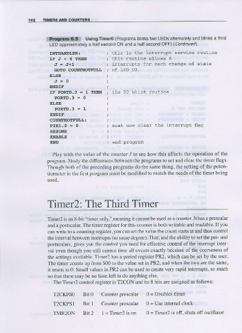
The Timer2 control register is T2CON and its 8 bits arc assigned as follows:
T2CKPSO Bit O Counter prescalar 0 = Disables timer
T2CKPS1 Bit I counter prcscalar 0 = Use intemal clock
TMR2ON Bit 2 I = Timer2 is on 0 = Timer2 is off, shuts off oscillator