
Page 113 - Making PIC Microcontroller Instruments and Controllers
P. 113
nMEn2! tHE THIFD TIMEB t03
value
TOUTPSo Bit 3 ) Counter postscalar
TOUTPSI Bit4 ) Counter postscalar
value
TOUTPS2 Bit 5 ) Counter postscalar value
TOUTPS3 Bit 6 ) Counler postscalarvalue
--------------+;
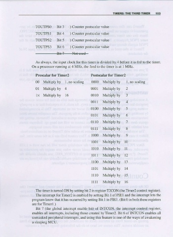
As always, the input clock for this timer is divided by 4 befor€ it is fed to the timer.
On a prccessorrunning at 4 MHz, the feed to the timer is at I MHz.
Prescalar for Timer2 Postscalar for Timer2
00 Multiplyby 1,no scaling 0000 Multiply by l, no scaling
0l Multiply by 4 0001 Multiply by 2
lx Multiply by 16 0010 Muldply by 3
0011 Multiply by 4
0100 Multiply by 5
0101 Multiply by 6
0l l0 Multiply by 7
0lll Multiply by 8
1000 Multiply by 9
l00l Multiply by l0
l0l0 Multiply by ll
1011 Muitiply by 12
I100 Multiply by 13
ll01 Multiply by 14
1110 Mulriply by 15
1111 Mulliply by l6
The timer is tumed ON by setting bit 2 in rcgister T2CON (fie Tiner2 control register).
The iftenupt for Timer2 is enabled by setting Bit I of PIE I and the intempt lets the
program klow that it has occuri€d by setting Bit I in PIR lr (Bit 0 in both these registers
ttre for Timerl.)
Bit 7 (the global intenupt enable bit) of INTCoN, the interupt control regisrer,
enables all inteffupts, including those created by Timer2. Bit 6 of INTCON enables a]l
unmasked peripheral intenupts, and sing this feature is one ofthe ways of awakening
a sleeDine MCU.