
Page 118 - Making PIC Microcontroller Instruments and Controllers
P. 118
{0s rl
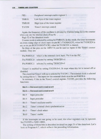
PIEI Peripherai inte upt enable register 1
TVRIL Lo$ bl|f, oflhe limer rcgisrel
TMR1H High byte ofthe timer register
TICON Timerl inteffupt control
Again, the frequency of tbe oscillator is djvided by 4 before being f-ed to the counter
when you use the intemal clock (Fosc/4).
Page 52 of the datasheet reads:
Counter mode is selecteal by setting bit TMR 1CS. In this mode, the timer increments
on every rising edge of clook input on pin RCI/IIOSI/CCP2, when bit T1OSCEN is
ser, or on pin RCO/T]oso/TlcKl, when bit TloscBN is clearcd
So three of the piDs on the l6F877A can be used as inputs to the Timerl counter
moduie. They are:
Pin PORTA.4 which is the extemal clock input. Pin 6 on the PIC
Pin PORTC.0 selected by setting TIOSCEN =1
Pin PORTC.I selected by setting TIOSCEN=o
Timcrl is enabled by setting T1CON.0=I. lt stops when this bit is tumed off or
disabled.
The clock that Timerl will use ls selected by T lCON.I The extemal clock is selected
by setting this to 1. The input ior this extemal clock must be on PORTB 4
In summary, 8 bits in the Timerl control register, TICON, provides lhe following
functions:
Bi{4-N#3-re€d.es-a-e
$46---+eg$ed*iid
Bit 5 Inputprescalar
Bil4 Input Fescalar
Bii 3 Timerl oscillator enable
Bit 2 Timerl extemal clock synchronizalion
Bit 1 Timerl clock select
Bit0 Timerl enable
If the interrupls are not going to be used, the othel rcgisters can be ignored
S e t T l C O N = E 0 0 1 1 0 0 0 1 .
The setting ofthese bits is descdbed in detail on page 51 ofthe datasheet. Let's
took at Program 6.?, which reflects the preceding information.