
Page 119 - Making PIC Microcontroller Instruments and Controllers
P. 119
cout{tEns t09
; Frrst 1et us deflne all the deines that {e si11 need,
; Here all lhe def,nes are included as an exanple bu!
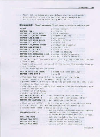
; nor all are needed when using the LAB X1.
l:?t!itii!i!;li:l Timerl as counter (T merl counts signats from a motorencoder)
CIJE]AR
DEFINE OSC 4 ; 4 MEz clock
DEFIIIE LCD DREG PORTD da.d r-g:s -
DEFIAIE LCD RSREG PORTE /E9' A '6'6'
DEFIAIE I]CD-RSBI![ O
DEFINE LCD-EREG PORIE ; enabLe reqisrer
DEFIAIE LCD.EBIII 1
DEFIIIE LCD-RttlRlc POREE ; read/vrite reqrsrer
DEFINE LCD_RWBT!! 2 ; read/vrite bit
DEFINE I,CD.BITS 8 ; tidth of data
DEFINE LCD-LINES 2 ; lines in display
DEFME IJCD_COMMANDUS
2000 , deray in micro seconds
DEFTNE IJCD_DATAUS 50 ; delay in micro seconds
: l - a - , r . / o l i n 6 e d 6 t u 6 1 r p _ n s 9 o , . 9 o o e
\
; that will control Lhe speed of the noLor. The encoder thaL we
; at rs allached to the noto.
DEFINE CCP1 REG PoRTC ; define the HPI,il,t setLings
DEFIIiIE CCPI BIT 2 ; pin C1
; I h - r - l r ' 6 r 6 o d 1 0
potentiometers on the board. Only lhe first
potentioneier is being used in the progran but Lhe orhers are
defined so rha! you can
6
, o - o o , Y I n 6 p o r r o - - a r - S i e
you vafues you can
change in real tine,
define the A2D waLues
DEFINE ADC BITS I ; set nun'ber of bits in xesulL
DEFTNE ADC CITOCR 3 ; set internaL clock source {3=rc)
mFINE ADC SAMPITEUS tine in uS
50 ; set sanpling
; Next we set ADCON1 to bring the MCU back inro diqitaL mode.
; Srnce lhis PIC has analoq capability, ir cones up in
; analog node after a rese! or on starrup.
; set the Analog lo Digiral cont.ol .eqister
A!COI{1=%00000111 ; needed for the LCD operation
; re create the variables rhat we wiLL need.
l[MRl VAR ]IORD ; ser rhe variabte for rhe riner
.A.DVAIJo VAR BYTE ; creare adwaL !o store resulL
A.DvALl VAR BYTE ; creaLe adwaL to store resulr
a.DvA!2 VAR BYTE , creare adwaL to store resulr