
Page 240 - Making PIC Microcontroller Instruments and Controllers
P. 240
'HE COUNTER$ COUNTI G ANBIES
23A U DENSTA|{DING
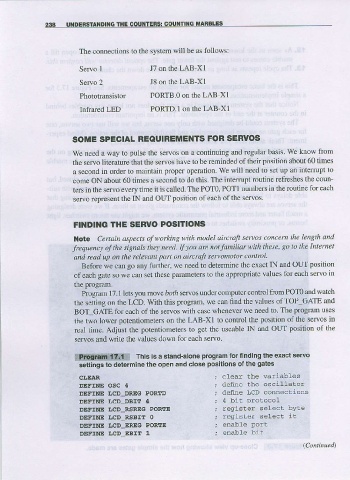
The connections to the system will be as follows:
S e o I J7 on the LAB-XI
Servo 2 J8 on the LAB-XI
Phototransistor PORTB.O on ihc LAB-XI
Infrared LED PORTD.I on the LAB-XI
SOME SPECIAL NEOUIREMENTS FOR SERVOS
We need a way to pulse the servos on a continuing and reguldr basis. We know liom
the servo literature that the servos have to be reminded of their position about 60 times
a second in order ro mrinuin proper opernlion We $ill nccd ro 'el up an intelrupl lo
come ON about 60 times a second to do this. The intefupt loutine refreshes the coun
ters in the se o every time it is caUed. The POTo. POT1 numbers in the routine for each
servo represent the IN and OUT posilion of each of the servos.
pOSlTlOl{S
FtNDtitG THE SERVO
Nole Cefiain dspects of v)orking with nodel aircrafr senos concern the LenSth and
lrcquenct of the sig%ls they need. IfJou an not familiar withthese, 80 to the lntenet
and read up on the relavant part on aircruft senomotor control.
Before we can go any furthet we need to determine the exact IN and OUT position
of each gate so we can sel these parametels to the appropriate values for each servo in
the program.
Program 17. I lets you mol'e ,otri servos under computer control from POm and walch
the setting on the LCD. With this program, we can find the values ofTOP GAIE and
BoT GATE for each of the se os with ease whenever we need to The program uses
the two lower potentiometers on the LAB-XI to control the positron of the setvos in
real time. Adjust the pot€nliometers to get the useable IN and OUT position of the
seNos and wnte the valu€s down for each servo,
Thls is a stand-alone program for linding the exact seruo
8*e.qfr&lfff}]
settings to determine the open and close posilions ol the gates
CI,EAR ; clear hhe variabLes
DEFINE OSC 4 ; denne the oscillator
DEFINE LCD_DREG PORTD ; define LcD comeccions
DEFINE LCD DBIII 4 ; 4 bit protocol
DET'INE I|cD RSF.EC PORTE ; register: selecL byte
DEFIIIE ITCD RSBIT O ; register select rt
DEFIIIE ',CD ERTG POREE
DEFINE IJCD EBIT 1