
Page 254 - Making PIC Microcontroller Instruments and Controllers
P. 254
252 Ul{DEnSlAllDltlG THE cou TERS: COU|{III|G ARBIES
The count will be displayed as 2 tbre€ digit single byte registers and will flow from
the low byte on the right to the high byte on the left every time the count in the low byte
spills over 255.
The counter indements every time line C.0 goes from 0 to 1. With dre first marble rcst
irg on top of the lower gate, the count is 0. As soor as the marble drops away, the count
goes to 1 It will stay at 1 till the second marble drops by. It will then go to 2 and so on.
The program needs to hold the lower gate closed and the upper gate open till you press
SW I to start the counting process. Once counting starts,the gates stay open till you reset
the system at the end of the count.
The entirc Fogram with the'\rait for SWl" added and the bit identification and some
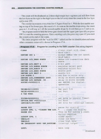
other comments removed is shown in Program 17.6.
Program for counting to theTMR1 counter (See wi ng diagram)
_ ' d
C L E j A R j d l s " Y ' . a ! . w t f .
; Good habi!.
DEFINE OSC 4 ; always define the osc speed.
, Good habi!
DEFINE LCD_DREG PORID ; defne LCD conneclions daLa
; PORTB
DEFINE LCD-...DBIT 4 ;4 biL Path
DEFIIIE I,CD_RSRIC PORTE SE. ECT DO'T
DEFTNE LcD-RsBrT 0 ; reqisber select bit
DEFINE LCD_EREG PORTE ; enable port
DEFINE I,CD EBIT L } enable bit
Itolf PORllE.2 ; se! tott to write only
DEFME IJCD COIIIIAIIDUS 2000 i d-l"v -n n:c-o se.olds
DEEINE LCD-DATAUS 50 ; delay in micro seconds
a!cON1=%00000111 ; set ADcoNl fot digiral
; operation
TRISB=%11110001 ; Set port I/O
tRtsc=?00001111 ; set Port
X VAR IIORD
rlCON-%00000011 ; se! bits to control Tinerl
OPTION_REG =%01111111 ; seL bits ' r L - ! t L p .
I N l T c o N = t s l o o l o o o o ; s . L o r s f o i ( o _ t _ o _ .
PAUSE 500 ; pause for. starlup
LCDOIX! $FE, 1. .CI,E,ARS IHE ICD. ' ; clear the display.
PAnsE 250 i lh s -. Ior seeirg d Fs'L
; I)ulcon response
LCDOUIIT sFE, L t clear again.
l'uRlL=o ; clear: 1ow byte
TMRlrr=o ; clear hiqh byle
ON IMIERRUPII GC':rO IMr_ROUI!NE; inLeriup! larget
LooP. ; nain loop
(ContirueA