
Page 255 - Making PIC Microcontroller Instruments and Controllers
P. 255
us[{G ttMERt |l{ couNtER iloDE 253
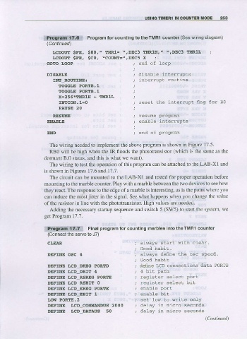
lit!!-g.t{Fi!1€'l Program for counting to theTMRl counter (see wiring diagram)
LCDOIXT gFE. $80." tltRl= \,DEC3 !rMR1H,, \,DEC3 E![RlI- ;
LCDOtt:l SFE, SCor \COIINI.=Z, DEC5 x ;
G(,IIO LOOP ; end of loop
DrsABr,E ; disable interrupls
t!fll ROUTINE: ; intedup! rouLrne
TOGGT,E PORTB.I
TOGGLE PORTB.I
x-256*EMR1g + tldRlL
t!fllcoN.l=o ; reset the interrupt flaq for BQ
PAUSE 20
REsttl@ ; resue Progrd
ENABLE ; enable inlerrupts
END ; end of Progran
The wiring needed to implement the above program is shown in Figure 17.5.
RBO will be high when the IR floods the phototransistor (which is the same as the
dormanr B.0.latus, and lhi\ i\ \ hal $e s.nll.
The wiring to test the operation ofthis program can be attached to the LAB-XI and
is shown in Figures 17.6 and 17.?.
The circuit can be mounted to the LAB-XI and tested for proper operation before
mounting to the marble counter Play with a marble between the two devices to see how
they react. The response to the edge of a marble i s i nteresting, as is the point where you
can induce the mostjitter in the signal. See what happens when you change the value
of the resistor in line with the phototransistor. High values are needed.
Adding the necessary startup seq ence and switch 5 (SW5) to siaft the system, we
get Program 17.7.
ilfi!0,iii.f.!jn$[li]1 Flnal program for countins madles Into theTMRl counter
(Connecl
the seruo to J7)
cLslaR ; always start with clear'
; Good habi!.
DEFINE osc 4 ; always defne the osc speed
, 'lood habil
DEFINE tCD DRES PORTD , deine LCD comections data PORTB
DEFINE LCD DBIT 4 ; 4 bit path
DEFINE I.cD RSREG PORTE . -og-s'AT SEI.'i DOI
DEFINE IcD-RsBrT 0 ; reqrister select bit
DEFINE I,CD_EREG PORTE ; ENAbIE POTT
DEFINE I,CD_EBIT t i enable bi]:
LOw PORTE.2 ; se! 1ow Lo vrite only
DEFINE LCD_COMMANDUS 2000 ; delay in nticro seconds
DEFMIE LCD_DATAUS 50 ; delay in nicro seconcls
(Cottituue.l)