
Page 265 - Making PIC Microcontroller Instruments and Controllers
P. 265
PnoJECT 4 263
0000 A A I X J A A A A Vdd Vss 8/0
0001 A A d Vrcf A A A FlA3 Vss 7ll
0010 D D D A I X J A A A A Vdd Vss 5/0
0011 D D D A lxJ Vrct A A A FA3 Vss 411
0100 D D D A lxl A D A A Vdd Vss 3/0
0101 D D D D lxl Vrcl D A A FA3 Vss 2ll
0110 D D D D I I , I A D D D Vdd Vss 0/0
0 1 1 1 D D D D I X I A D D D Vdd Vss 0/0
1000 A A /x./ Vref Vref A A RA3 RA2 612
1001 D D A A I t J A A A A Vdd vss 6/0
1010 D D A A lxl Vtel A A A BA3 Vss 5/1
1011 D D A A d V r e f v r e l A A RA3 RA2 4/2
1l00 D D D A d Vref Vrel A A RA3 RAz 3/2
1 1 0 1 D D D D r d V r c t v r e i A A RA3 RA2 212
1 1 1 0 D D D D I X J D D D A Vdd Vss 1lO
' 1 1 1 1
D D D D /, Vrei Vrel D A aA3 RA2 112
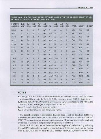
NOTES
t. Sellings 0l l0 and 0l ll have idcntical res lts but afe both showD, so all 16 conbi
nalions will bc sccn in thc Tablc 18.2. The datasheet shows 0l lX for both lines.
2. Beware tharANT loANo arc thc scvcn.rral{rg irlirt i dentifications and Port E.2 to
E.0 and A.5 toA.0 are ptn identifications onthe PIC.
3. A-l lr nis.!ln8 in this se{, as stated eaflier
4. Do not totlfule the lins wilh the analog inp ts.
Thc prcccding setting i s described in detail on page I I 2 of the datasheet. Table I 8.2
is a short fbrm of that table. we do not have I/O access to lines A.7 andA.6 on lhc PIC
16F877A because they are internal to the processo.. (They can. however. be rcad, and
arc rclatcd to lhe use ofihe parallel pofi capability ofthe PIC.)
In our particularcasc. |!c arc intcrcsted in aking pinsA0 and Al aralog ard using
Vss aDd RA3 as therelerence vollages lo which wc will cornpare the signal\\,e receive
from the LM34s. Since we have the LCD connected 10 PORTE. wc need its pins to be