
Page 268 - Making PIC Microcontroller Instruments and Controllers
P. 268
Using the same addresses used by the LAB'XI lets us test our sottware on a
syslem we krow to be operating properly. Just knowing that the software will send
somelhing to t}te display can be heartening for a beginner' Once our confidence
level rcgarding lhe use oithese microcontrollers gets higher. we car abandon this
strategy.
It is a gooil ialea to take the time to add lhe ten pin connectol that allows us to pro-
gram the PIC wiihoutremoving it liom the bodrd we are working on. This makes itjust
about painless to make changes to the soltware, and in areally useful instrument (that
you yourselfhave designed and built and thus know intimately about) this is a power-
ful leature that dllows you to modify the chatacteristics of the instrument whenever you
need to with a few keystrokes.
Another very useful adj unct to the hardware is to provide an addi tional input line and
output line. These two lines can then be programmed to intefactwith the instrumentwe
have created and would allow us to rcspond to a signal coming in on the input line and
express the response on the output line aftcr we had processed the idomation from the
If we replace one of the sensors wilh a potentiometer, we can control the signal
coming in on that sensor pin. Meaning, of course, that we can set one sensor inp t to
whatever value we want with the potentiomeler This value can then be used as a set
point that the other sensor reading is comparcd to before deciding whether we want 1o
make our outpul line go high or low.
We have now tumed our instrument into a very easy to-set thermostat.Ifwe like,
this thermostat can be controlled ffom our auxiliary input line and the input line can
get its signal from a remote source (maybe even over the Intemel !) Keep in mind that
we arenotlimitedto using single lire inputs and outputs. Our imagination is the only
limit.
The instrument we created is more powerlul and more flexible than that The signal
we send out can be a pulse width modulated (PWM) signal, where the level of modu-
lation is a function of how far the set point is from the desired condilion lt could be a
frequency we might want to broadcast to the world-and so lhe beginnings of intelli
gent control start to come together.
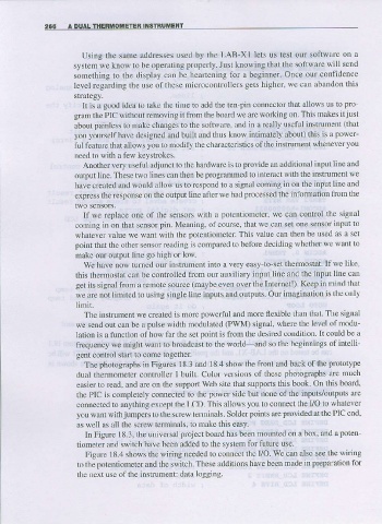
The photographs in Figures 18.3 ard 18.4 show the front and back of the prototype
dual thermometer contrcller I built. Color versjons of these photographs are much
easier to rcad, and are on the support Web site fhat suppofts this book On this board'
the PIC is completely connected to the power side but none of the inputs/outpuls are
connected to anything except the LCD. This allows you to connect the VO to whatever
you want with jumpers to the screw tenninals. Soider poinls are provided at the PIC end.
as well as all the screw lelr)linals, to mate this easy.
In Figure I8.3, the u versal ptoject bodrd has been mounied on a box, and a poten-
tiometer and switch hal'e been added to the system for future use.
Figure 1 8.4 shows the wiring needed to conncct the VO We can also see the wiring
to the potentiometer and the switch. These additions have been made in preparatjon for
the next use olthe instrumenl data logging.