Page 273 - Making PIC Microcontroller Instruments and Controllers
P. 273

aN aRTIFICIAL  HoRlzoI!  a TABLE SUnFACE  tlulT  sTAYs LEVEI


                                                                    -o
                                                                  I
                                                                    o
                                                                    oo
                                                                    -o


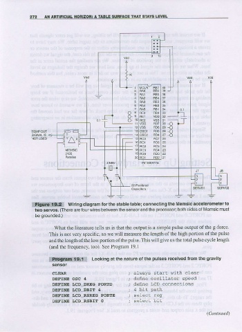
              lttffiitii5gial   wiring diagram forthe stable  lable; con necling the  Memsic accelerometerto
               two servos.  (There  are four wires belween the sensor  and the  processor;bolh   musl
                                                                           sides ol l\4emsic
               be  grounded.)

                       What the lilerature lells us  is that the output is a simple  pulse  output of the  g-force
                     This  is not very specific, so we will measure the length of the high  porLion  of the  pulse
                     and the  length of the low portion  of the  pulse.  This will give  us  the totrl pulsc  cycle  length
                     (and  the frequency,  too). See Program  19.1

                                      Looking at the nalure of lhe pulses received  from the gravlty
                     |i!i!l!.8iin$*fl

                      CLE]AR
                      DEFINE  OSC  4                  deflne osciLlator   speed
                      DEFINE   I,cD  DREG  PORTD      deine  LCD connections
                      DEFINE   I.CD  DBIT   4
                      DEFIIIE   I.CD  RSREG  PORTE
                      DEFTNE  I.CD  RSBIT  O
   268   269   270   271   272   273   274   275   276   277   278