
Page 275 - Making PIC Microcontroller Instruments and Controllers
P. 275
2t. ll| AntFrcnL HOnEO|.: A l ElE SIIRFACE tllAl SIAYS IEVEI
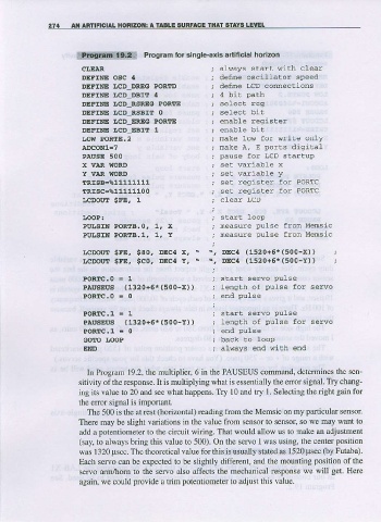
Program for single-axis a ificial horlzon
c l , s A R : a h a y s s r a ' r k : r h c l e a r
DEIINE osc 4 i defne oscillacor speed
DEFTNE I.D DREG PORTD ; dEf,NE I,CD COMECTiONS
DEFTNE LD DBI! 4 ; 4 bit Path
DEFltrE LCD RSREG PORTE ; se.Lect reg
DEFINE tcD RgalT 0 ; selecl bil
DEFTNE LCD ERIG PORTE ; enqbre regisEe-
DEFINE LCD EBII L i enable bit
r,o!{ PoRIE.2 ; make low fot write only
A!CONl=7 ; rnake A, E porCs digitat
PAUSE 500 ; pause for LCD startup
x VAR IIORD , set variabre x
Y vAR lloRD ; set variable Y
TRISB=ts11111111 ; sel ..eg:ster 'o_ DORTC
TRISC-%11111100 ; se. leg-sLer 'o. PORTC
LCDOUT SFE. 1 ; clear LCD
IOOP: ; star! loop
Pul,gtN PoRIE.O, 1, 1t ; neasure pulse from Mensic
PULSIN PoRtB.l, 1, Y ; neasure pulse fron Mensic
&cDotrr sFE, s80, DEc4 :<, \ \, DEc{ (1520+5r(s00-x)) }
ncDorrr sFE, sgo, DEc{ Y, . ", DEc{ (1520+5t(500-l)) i
PORIC.o = 1 ; start servo Pulse
PAusEUs (1320+6*(500-x)) ; lenqth of pulse for serwo
PORIC.o = 0 ; end pulse
PORI{,I = 1 ' star! servo pulse
PrusEus (1320+5*(s00-Y)) ; length of pulse for servo
POREC,I = 0
GOIO I,oOP
EIID ; ahrays end with end
In Program 19.2, the multiplier 6 in the PAUSEUS command, determines the sen'
sitivity ofthe response. It is multiplying what is essentially the error signal. Try chang-
ing its value to 20 aod see what happens. Try 10 and try l. Selecting the dght gain for
rhe error signal is imponanl.
The 500 is the at rest (horizontal) reading from the Memsic on my pafticular sensor.
There may be slight variations in the value from sensor to sensot so we may want to
add a potentiometer to the circuit wiring. That would allow us to make an adjustment
(say, to always bring this value to 500). On the servo I was using, the center position
was I 320 psec. The theoretical value for this is usually stated as 1520 psec (by Futaba).
Each servo can be expected to be slightly different, and lhe mounting position of the
servo arm/horn to the servo also affects the mechanical response we will get. Here
again, we could provide a tdm potentiometer to adjust this value.