
Page 274 - Making PIC Microcontroller Instruments and Controllers
P. 274
SEIIIIIG UP THE HARDWARE CONI{ECTIOI{S
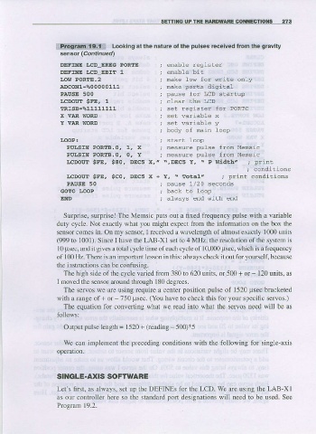
r,lPngtiinii{9.ilitt Looking al the nature ol the pulses received from the gravily
sensor rcof,trued)
DEFXNE I.CD ERIG PORTE enable reqister
DEFINE I,CD EBIT 1
I,OW PORTE.z nake Lor for rrrte onLy
ADcoNl=%00000111 nake ports digital
PAUSE 5OO pause fo! LcD startup
r,cDour *FE, 1
TRISg=%11111111
X VAR WORD set wariabLe x
Y VAR IIORD set wariable y
body of frain loop
LOOP:
PULSIN PORTB.O, 1, X neasure pulse fron Mensic
PUITSIN PORTB.O. O, Y neasure pulse fron Mensic
LCDOTXf SFE, SAOI DECS X?z $,DEC5 Y, - P wiilth,, ; print
, conditions
LCDOLT $FE, $C0, DECs x + Y , \ T o t a l z ; print conditions
PAUSE 50 ; pause 1/20 seconds
eo4ro LooP
E]ND ; always end riith end
Surpise, suryrise!The Memsic puts out a fixed frequency pulse with a variable
duty clcle. Nol exaclly whal you mighl cxpccl from the information on the box the
sensor cornes in- On my sensor, received a wa\,elength ol almost exactly 1000 units
I
(999 to 1001). Since I have the LAB-XI set to 4 MHz. the resolulion of the system is
l0 psec, and it gives a total cycle time of each cycle of 10,000 psec, which is a frequency
of 100 Hz. There is an impofant lesson in this: always check it out for yoursell, because
the instructions can be confusing.
The high sidc ofthe cycle varied from 3801o 620 units. or 500 + or 120 units, as
I noved (he sensor alolmd thlough 180 degrecs,
The servos we are using require a center posilion pulse ol 1520 psec bracketed
with a range of + or - 750 Usec.
(You have to check this for your speciiic selvos.)
The equation for convefting what we read into what the servos need will bc as
lbllows:
Output pulse length = 1520 + (reading - 500)*5
Wc can implement the preceding corditions with the following for single-ais
operadon.
SINGLE.AXIS SOFTWARE
Let's first. as always, set up the DEFINES for the LCD. We are using the LAB Xl
as our controller here so the standard port designations will need to be used. See
Program 19.2.