
Page 266 - Making PIC Microcontroller Instruments and Controllers
P. 266
264 ADUALTHERMOMETENIISTNUMEG
digital. At this time,lhe status of the other lincs is ofno interest to !rs. The lines can be
sei to analog by selecting li ne 4 or 6 in the Table 1 8 2 For our purposes' which include
using the LCD. all other lines can be digital. Ausefnl selection is lit?e l, which makes
all of PORTA analog and all of PORTE dlgital ln our case. POmA 3 will be used as
the relcrence voltage to which the incoming signals will be compared We would spec
ify thalADCON1 bc set as follows:
aDcoNl='ao0000011 or aDcoNl=3
(ADCONI=8600000111. which is used droughoul this book to match the nsual
Labs seltings:it sets aU thcAand E lhcs 10 digilal )
nicroEngineering
As shown in the wi ng diagnm, the output from the two LM34s will be led into lhe
16F877Aat PORTA on linesA0 and AI
Notice thal the way we are wiring in the LM34s is identical to the way we wire rn
a potentiomelcr ln either case, the device is placed between the high and low-power
supply rails, and we read what is the equivalent oflhc wiper. Thjs is the standard way
of reading a voltagc into a PIC microconlroller' If other than 0lo 5 volts are to be read
in, appropriate voltage dividers and the nccessarl safety precautions have to be pro_
vided.ln ourcase, we will use pin A.3 as thc reference voltage, and the voliage on lhis
pin can be adjusred wjth the polentiometer provided lbr this purpose See the earlier
diagram in Figure 18.2. The pins that the refcrence voltages are impressed on musl
be selected as indicated in Table 18.2 meaning that only A 2 and A 3 can be used
Lct's write the program to display the two signals on the 2line by-16-character
display we are using for oulput. The display is to read as follows:
Temperaturcs
123'F 123'T'
Provide two spaces on the left olthe display so the display is centered in the LCD
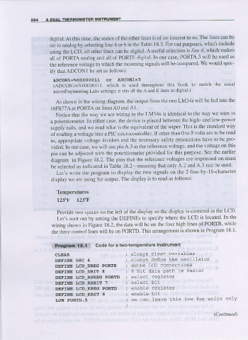
Lefs strr! out by setdng the DEFINES to specify where ihe LCD is located ln the
wiring shown in Figure 18.2. the data will be on thc four high lines oI PORTB, while
is shown in Program 1 8 1
the th;ee control lines will be on PORTD This arrangement
,:F.Or€4':!9ir:r Code for a two{emperaiure instrument
CI.EAR alvays clear variables
DEFIT|IE OSC 4 aLways define the oscilLatoi
DEFIIIE IJCD DREG PORIB define LCD connecLlons
DEFII.IE 'JCD DBIT 8 8 bit data PaLh is faster
DEFINE IJCD RSREG PORTD select reqasler
DEFIIIE IJCD RSBIT 7
DEFINE IJCD-EREG PORTD enable register
DEFINE ',CD-EBIf 5
LOW PORTD.5 we can leave this 10{ for write onLY