
Page 67 - Making PIC Microcontroller Instruments and Controllers
P. 67
FEAOII{G A P]OTEIITIOMETER AI{D DISPLAYING II{E RESIIITS ON THE fEO BANGNAPH
(65,535) and integer math in PICBASIC. BIN16canbe used for 2-byte words to display
all 16 bits. Any number of digits up to 16 canbe displayed.
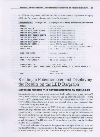
ill!.ijliilii.i:.qoall writins io the LcD dispray in FULL b;nary hexadecimar, and decimal
CLEAR
DEFINE OgC 4
DEFINE IJCD DRIC POR'D deine LCD connections
DEFINE LCD_DBIT 1I def,ne LcD connections
DEFINE I]CD RSREG PORTE define LCD connections
DEFINE IJCD_RSBIT O def,ne LcD connections
DEFINE I,CD EREC PORTE define LCD connections
DEFINE LCD EBIT 1 deflne LCD conneciions
ADCON1-%00000110 rnake PoRTA and PORTE dlgiraL
IOIT PoiRTE.2 rcD R/\'i 1ow ('rite) We will do no xeadins
PAUSE 500 wait for LCD to starL up
NMAR VAR BYTE assign variable
TRISD = %00000000 D7 D0 = all outpuls
NMBR = %10101010 this is decimal 170
r.cDou! $FE, $80, BrNS i{MBR, z \,HEX2 NUBR, . ., DEC5 N!|BR, " .
; display
END ; end proqran
Reading a Potentiometer and Displaying
the Results on the LED B
OTES OI{ READII{G THE POIENIIOiIETERS OI{ TIIE LAB-Xt
Each potentiometer i s placed across ground and 5 volts alrd the wiper is read on the A/D
line. (Other reference voltages and resistances can be specified and used-see the
datasheet.) The potentiometer value has to be high enough so as not to act as a short
between the power and ground. 5K ohms as a minimal value is okay. (Extremely high
values make for a jittery reading.)
When we read a potentiometer the MCU divides the voltage across the potentiome-
ter into 256 steps beiween 0 and 255 and gives us the number that represents the posi-
tion ofthe wiper across the connected voltage. Neither the voltage nor the resistance of
the potentiometer s relevanl (thoughitcan be if we know theminimum and maximum
i
voltage across the pot). What we are getting is the relative position of the wiper expressed
as an 8-bit number. (The PIC also has a 10-bit resolution capability see the datasheet
and PICBASIC manual.)
The overall resistance of each of the three potentiometers is placed across 5 volts, and
lhe three PORTAlines read the position oithe three pers. The potentiometers ar€ read
as s-bit values using an s'bitA to D converter This gives a full-scale reading of from