
Page 71 - Making PIC Microcontroller Instruments and Controllers
P. 71
A SIiIIPLE BEEP 6i
It dennes that we are using a4 MHz oscillaror
PORTC.2 specifies the pin to be used.
127 specifies a 50 percent duty cycle; the range of the variable is from 0 to 255.
I 00 specifies that the tone is ro last for 100 of rhe 256 ON-OFF steps rhat define one cycle.
In the PWM command, the fiequency and lcngth of the signai generated are dependenr
on the oscillator frcquency. In our case, this is 4 MHz, and one cycle is about 2.5 milliseconds
long (0.0025 secondt.
Note that the line C2 is also connectcd to the output for a possible phonejack and to
an IR LED that can be used to interact with IR receiven. These rwo connections ate
not populated on the PC board as received but they can be added without diificulty.
Two fypes of signals can be annunciared on rhe speaker as prcgrammed from the com-
piler The PWM commaod can send a signal of a fixed duty cycle ior a fixed number
of cycles, and the HPWM command can set up a PWM signal thal nns continuouslt
in the backgmund.In eilher case, the signal needs to be Fovided on the PORTC.2 pin
because that is where the speaker is connected. However the normal pWM (nor rhe back-
ground IIPWM) conrmand signal can be made to appear at any available pin. The back
"on
ground HPWM signal can be modified the fly" in a progl:rm.
The HPWM signals can only be made available ar pin PORTC.2 (Channel t) and
PORTC.I (Channel2). Yes, the pin nurnbers are reversed! In the PIC 16F877A, rlrcre
are only two IIPWM channels and rhese two pins are connected pemanently to these
twochannels. (SomePIC devicesprovide more than two channels. See the datasheets.)
Since we have the speaker hardwired to PORTC.2, we can only use HPWM Channel I
tbr the tones we generate,
As seen in Figure5.5, these signals can also be used to generate telephone dial tones
(DTMF) and inftared (IR) signals when provided wirh rhe appropriare hardware. We
will concentrate on creating tones on the piezo speaker The w ing and programrning
is the same for the other devices; they are all wircd in parallel. Just change ihe param-
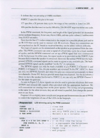
Progran 5.8 is a slightly more compljcated program and demonstrates the use of PWM
to control the brightness of one of the LEDS in the bargraph.
pwM
iqtiimff5igt LED dimming usins the command
CI.EAR
DEFINE OEC 4
ERISD : %U111110
X VIR BYTE
I.OOP:
FOR x = 0 IO 255 STEP 5
Pt{!r PoRTD.o, X, 3
NEXT X PORTD. O
Gdro tooP
END