
Page 68 - Making PIC Microcontroller Instruments and Controllers
P. 68
COI{TNOLLING THE OUTPUT AND REAOITIG THE INPUT
0 to 255 for ail duee potentiometen, no matter what the actual total rcsistarce value of edlh
potentiometer. If you want to read the resistance in ohms, you must divide the reading by
255 and mulriply by the lotal resistance olthe potentiometer (Again, the potentiometer
value must be high enough so the potentiometer does not act as a shon bctween glound
and the MCU power comeclion. 5K lo 10K ohms is a good seleclion for most purposcs.)
Next, we will rcad just one of the potentioneten (the one nearest the edge of the board)
to an accuracy of 8 bits and display the results on the rightmost eight LEDS of the LED
bargraph. This potentiometer is connected to pin 2 ofthe PIC (also identified as RAo
and as pin PORTA.0). We will display the result of the value read (0 to 255) on the bar-
graph by loading the reading inlo PORTD. Since PORTD is connected to the eight
LEDS, this will automatically give us a binary rcpresentation oi the data. ln the next step,
we will display the inlormation on the LCD dispiay as alphanumeric data (which js, of
course. rnuch easier to read).
Exp.ndi4 the prcgram to not only disptay b the baryraph but also put the information on
the LCD display, we have a prcblem in that the PORTD lines are sharcd by rlre bargmph and
fie LCD display- When we run the program, we will notice ilat dEre is a backgmund noisy
blinking of the LEDS in the bargraph as the l,CD is uritten to, b t atur that is done the bar-
graph displays the data lrom the potentiometer as expected. If we had hardware and software
that could suppress thc LEDS whcn wc were writing to lhe LCD, this problem could be elim-
inaled. The opention observed demonslrates du1 the chip select line allows us to use the lines
of PORTD to control both the I-ED ba€raph and the LCD display. Once we are done with
writing to the l-CD we can load the data into POR'ID and pause the pogmm to allow us lo
read the display. Notice that the pause/delay must come immediately after setting PORTD to
A2D Value for this to work properly. when we do wha!, is important when using micrccon-
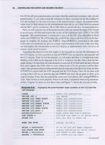
trollers. Program 5.6 shows us how this is done and Figure 5.4 shows the rclevant cinruiiry.
l:lpiiltriiiiilEii Disprayins thepotentiometer wiper position on the LCD and the
LED bargraph
CI,EAR ; def,ne LCD connections
DEFINE OgC 4
DEFINE I.cD DREG PORTD ; deflne LcD connections
DEFINE I,CD_DBIT 4 , denne LcD connections
DEFINE I,CD_RSREG PORTE ; deine LCD connections
DEFINE I.CD RSBTE O ; deine LcD connections
DEAINE I.CD EREG PORTE ; def,ne LcD connections
DEFINE I.CD EBIT 1 ; def,ne LcD connections
A.DCONI=?0 0000110 ; Make PORTA and PORTE digila1
IJOW PORTE.2 ; LCD R/W low (set it to write only)
PAUSE 5OO ; wait for LcD to start up
NUIIB VAR BYTE
IRtsD = %00000000
A2D VAI.UE VAR BYTE to store resuLt
IRISA = %11111111
A.DcONl = %00000010 ; se! poRTA analog