
Page 177 - Making things move_ DIY mechanisms for inventors, hobbyists, and artists
P. 177
Chapter 6 Options for Creating and Controlling Motion 155
2. Plug the DC toy motor wire leads into the rows next to pins 3 and 6 on the
H-bridge. Refer to the top image in Figure 6-21 to see which pin is which.
3. Solder jumper wires onto your SPDT switch. The example uses red for each
side and black for the center (ground) leg.
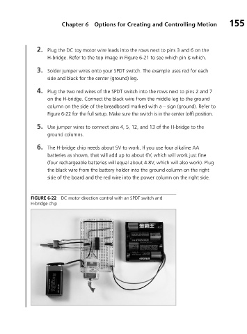
4. Plug the two red wires of the SPDT switch into the rows next to pins 2 and 7
on the H-bridge. Connect the black wire from the middle leg to the ground
column on the side of the breadboard marked with a – sign (ground). Refer to
Figure 6-22 for the full setup. Make sure the switch is in the center (off) position.
5. Use jumper wires to connect pins 4, 5, 12, and 13 of the H-bridge to the
ground columns.
6. The H-bridge chip needs about 5V to work. If you use four alkaline AA
batteries as shown, that will add up to about 6V, which will work just fine
(four rechargeable batteries will equal about 4.8V, which will also work). Plug
the black wire from the battery holder into the ground column on the right
side of the board and the red wire into the power column on the right side.
FIGURE 6-22 DC motor direction control with an SPDT switch and
H-bridge chip