
Page 180 - Making things move_ DIY mechanisms for inventors, hobbyists, and artists
P. 180
158 Making Things Move
P roject 6-6: Use Hardware PWM to Control Speed
You can create a PWM signal with hardware—that is, components you can hold—or
in software. We’ll start with the hardware version by building a circuit around a chip
called a 555 timer to create the PWM signal. 5, 6
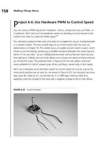
You will need a potentiometer and a transistor to complete this circuit. A potentiometer
is a variable resistor. The two outside legs act as a fixed resistor (like the ones we
talked about in Chapter 5). The middle leg is a movable contact called a wiper, which
moves across the resistor, producing a variable resistance between the center leg and
7
either of the two sides. So our 100KΩ potentiometer will act like two fixed resistors
that add up to 100KΩ, and the knob allows us to choose the values of those resistors
by moving the wiper. The potentiometer in Figure 6-24 has red, yellow, and black
wires soldered to it (which appear gray, white, and black, respectively, in the figure).
We’ll use a transistor as an electronic switch to connect parts of a circuit, just as the
mechanical switches we’ve used do. As shown in Figure 6-25, the transistor has three
legs: base (B), collector (C), and emitter (E). In an NPN type transistor (like this),
applying a positive voltage to the base and a negative voltage to the emitter allows
FIGURE 6-24 A potentiometer