
Page 183 - Making things move_ DIY mechanisms for inventors, hobbyists, and artists
P. 183
Chapter 6 Options for Creating and Controlling Motion 161
4. Connect pin 1 to ground.
5. Connect pin 2 and pin 6 of the 555 timer with a short jumper.
6. Also connect pin 2 to one of the outside legs of a potentiometer.
7. Also connect pin 2 through a 0.1 μF capacitor to ground.
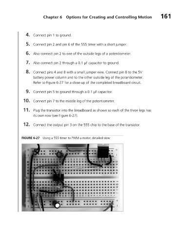
8. Connect pins 4 and 8 with a small jumper wire. Connect pin 8 to the 5V
battery power column and to the other outside leg of the potentiometer.
Refer to Figure 6-27 for a close-up of the completed breadboard circuit.
9. Connect pin 5 to ground through a 0.1 μF capacitor.
10. Connect pin 7 to the middle leg of the potentiometer.
11. Plug the transistor into the breadboard as shown so each of the three legs has
its own row (see Figure 6-27).
12. Connect the output pin 3 on the 555 chip to the base of the transistor.
FIGURE 6-27 Using a 555 timer to PWM a motor, detailed view