
Page 184 - Making things move_ DIY mechanisms for inventors, hobbyists, and artists
P. 184
162 Making Things Move
13. Connect the emitter leg of the transistor to ground.
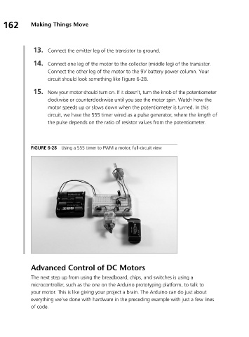
14. Connect one leg of the motor to the collector (middle leg) of the transistor.
Connect the other leg of the motor to the 9V battery power column. Your
circuit should look something like Figure 6-28.
15. Now your motor should turn on. If it doesn’t, turn the knob of the potentiometer
clockwise or counterclockwise until you see the motor spin. Watch how the
motor speeds up or slows down when the potentiometer is turned. In this
circuit, we have the 555 timer wired as a pulse generator, where the length of
the pulse depends on the ratio of resistor values from the potentiometer.
FIGURE 6-28 Using a 555 timer to PWM a motor, full-circuit view
Advanced Control of DC Motors
The next step up from using the breadboard, chips, and switches is using a
microcontroller, such as the one on the Arduino prototyping platform, to talk to
your motor. This is like giving your project a brain. The Arduino can do just about
everything we’ve done with hardware in the preceding example with just a few lines
of code.