
Page 187 - Making things move_ DIY mechanisms for inventors, hobbyists, and artists
P. 187
Chapter 6 Options for Creating and Controlling Motion 165
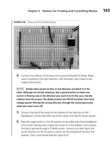
FIGURE 6-30 Close-up of the transistor wiring
4. Connect the collector of the transistor to ground through the diode. Make
sure it’s pointing in the right direction, with the stripe mark closest to the
middle of the board.
NOTE Diodes allow power to flow in one direction and block it in the
other. Although not strictly necessary, this is good practice to make sure
current is flowing only in the direction you want it to (in this case, into the
collector from 9V power). The diode protects the TIP120 transistor from back
voltage (power flowing the wrong direction through the motor) generated
when the motor turns off.
5. Connect one leg of the motor to the collector of the transistor on the
breadboard. Connect the other leg to the column with the 9V battery power.
6. Place the toggle switch (in the off position) on the other side of the breadboard
and connect one leg with a signal wire to pin 2 on the Arduino. Also connect
this leg to ground through a 220KΩ resistor. Connect the other leg of the
switch directly into the 5V power column on the breadboard fed from the
Arduino. Your circuit should look like Figure 6-31.