
Page 263 - Making things move_ DIY mechanisms for inventors, hobbyists, and artists
P. 263
Chapter 8 Combining Simple Machines for Work and Fun 241
transfer to the follower. The cam can also be a disk mounted off center (eccentric
cam), in which case the throw is just the difference between the maximum and
minimum distances to the axis of rotation. The follower can be flat, like the translating
cam in Figure 8-2 (left); it can end in a roller, like the oscillating cam in Figure 8-2
(right); or it can take the shape of a curved surface or hemisphere.
The cam shaft is the rotating input shaft that makes the cam spin. When the follower
creates linear motion, there is usually a shaft or stem guide to channel this motion.
The followers in Figure 8-2 rely on gravity to hold them against the cam, but could
also be spring-loaded.
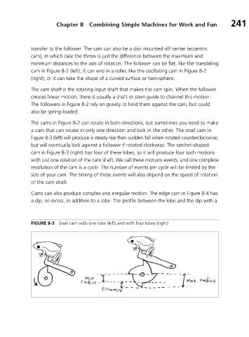
The cams in Figure 8-2 can rotate in both directions, but sometimes you need to make
a cam that can rotate in only one direction and lock in the other. The snail cam in
Figure 8-3 (left) will produce a steady rise then sudden fall when rotated counterclockwise,
but will eventually lock against a follower if rotated clockwise. The ratchet-shaped
cam in Figure 8-3 (right) has four of these lobes, so it will produce four such motions
with just one rotation of the cam shaft. We call these motions events, and one complete
revolution of the cam is a cycle. The number of events per cycle will be limited by the
size of your cam. The timing of these events will also depend on the speed of rotation
of the cam shaft.
Cams can also produce complex and irregular motion. The edge cam in Figure 8-4 has
a dip,or recess, in addition to a lobe. The profile between the lobe and the dip with a
FIGURE 8-3 Snail cam with one lobe (left) and with four lobes (right)