
Page 356 - Making things move_ DIY mechanisms for inventors, hobbyists, and artists
P. 356
Appendix: BreadBoard Power and Arduino Primer 333
based on C/C++. A set of instructions that you create in the IDE is called a program or
a sketch. Let’s try an example to get familiar with this language.
1. Open the Blink example by navigating to File | Examples | Digital | Blink. This
will open in a new window.
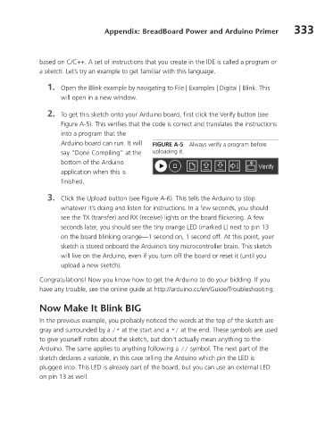
2. To get this sketch onto your Arduino board, first click the Verify button (see
Figure A-5). This verifies that the code is correct and translates the instructions
into a program that the
Arduino board can run. It will FIGURE A-5 Always verify a program before
say “Done Compiling” at the uploading it.
bottom of the Arduino
application when this is
finished.
3. Click the Upload button (see Figure A-6). This tells the Arduino to stop
whatever it’s doing and listen for instructions. In a few seconds, you should
see the TX (transfer) and RX (receive) lights on the board flickering. A few
seconds later, you should see the tiny orange LED (marked L) next to pin 13
on the board blinking orange—1 second on, 1 second off. At this point, your
sketch is stored onboard the Arduino’s tiny microcontroller brain. This sketch
will live on the Arduino, even if you turn off the board or reset it (until you
upload a new sketch).
Congratulations! Now you know how to get the Arduino to do your bidding. If you
have any trouble, see the online guide at http://arduino.cc/en/Guide/Troubleshooting.
NowMakeItBlinkBIG
In the previous example, you probably noticed the words at the top of the sketch are
gray and surrounded by a /* at the start and a */ at the end. These symbols are used
to give yourself notes about the sketch, but don’t actually mean anything to the
Arduino. The same applies to anything following a // symbol. The next part of the
sketch declares a variable, in this case telling the Arduino which pin the LED is
plugged into. This LED is already part of the board, but you can use an external LED
on pin 13 as well.