
Page 247 - Managing Global Warming
P. 247
206 Managing Global Warming
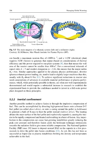
Inner poloidal field coils
(primary transformer circuit)
Poloidal magnetic field Outer poloidal field coils
(for plasma positioning and shaping)
Resulting helical magnetic field Toroidal field coils
Plasma electric current Toroidal magnetic field
(secondary transformer circuit)
Fig. 5.3 The main magnets of a tokamak system (left) and a stellarator (right).
Courtesy: EUROfusion, Max Planck Institute for Plasma Physics (IPP).
2
can handle a maximum neutron flux of 4MWm , and a 1-GW (electrical) plant
requires 3GW (fusion) to generate that output (based on considerations of thermal
efficiency and the power required to run plant systems [8], then that means the wall
2
area of the reactor cannot be smaller than 600m . For a conventional tokamak of
aspect ratio A ¼3 and modest elongation (κ ¼1.6), this means that the major radius
R 0 >6m. Similar approaches applied to the plasma physics performance, divertor
(plasma exhaust) power loading, etc. tend to lead to slightly larger machines than this,
usually with R 0 about 8–9m [11]. To achieve significant reductions in reactor size
needs assumptions of advances in available material performance or plasma perfor-
mance, which, while potentially possible in theory, are often not well experimentally
demonstrated and would require a substantial increase in research to establish the
experimental basis to provide the confidence needed to invest in a full-scale power
plant designed on these principles.
5.2.2 Inertial confinement
Another possible method to achieve fusion is through the implosive compression of
fuel. This can be accomplished by directing high-powered lasers onto a frozen D-T
fuel pellet (so-called direct drive), or onto a casing around the pellet (a hohlraum)
to generate a bath of X-rays to heat the pellet instead (indirect drive). The heating
ablates the outer surface of the fuel pellet and explosively expands it, causing the inte-
rior to be rapidly compressed and heated and resulting in a burst of fusion. Any imper-
fection in the compression can cause fast-growing instabilities greatly reducing the
peak core pressure and therefore fusion yield; the hohlraum technique intrinsically
smooths the radiation field to give more reliable compression. The National Ignition
Facility (NIF) uses 192 lasers to deposit around 20kJ on the capsule in a few pico-
seconds to drive the pellet into fusion conditions [12]. As yet, this has not been as
successful as hoped due to plasma instabilities limiting the density and temperature
achievable in the fuel.