
Page 318 - Manufacturing Engineering and Technology - Kalpakjian, Serope : Schmid, Steven R.
P. 318
Section 12.2 Design Cons|derat|ons |n Casting 2
TABLE l2.l
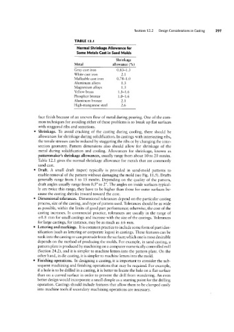
Normal Shrinkage Allowance for
Some Metals Cast in Sand Molds
Shrinkage
Metal allowance (%)
Gray cast iron 0.83-1.3
White cast iron 2.1
Malleable cast iron 0.78-1.0
Aluminum alloys 1.3
Magnesium alloys 1.3
Yellow brass 1.3-1.6
Phosphor bronze 1.0-1.6
Aluminum bronze 2.1
High-manganese steel 2.6
face finish because of an uneven flow of metal during pouring. One of the com-
mon techniques for avoiding either of these problems is to break up flat surfaces
with staggered ribs and serrations.
Shrinkage. To avoid cracking of the casting during cooling, there should be
allowances for shrinkage during solidification. In castings with intersecting ribs,
the tensile stresses can be reduced by staggering the ribs or by changing the inter-
section geometry. Pattern dimensions also should allow for shrinkage of the
metal during solidification and cooling. Allowances for shrinkage, known as
patternmaker’s shrinkage allowances, usually range from about 10 to 20 mm/m.
Table 12.1 gives the normal shrinkage allowance for metals that are commonly
sand cast.
Draft. A small draft (taper) typically is provided in sand-mold patterns to
enable removal of the pattern without damaging the mold (see Fig. 11.5 ). Drafts
generally range from 5 to 15 mm/m. Depending on the quality of the pattern,
draft angles usually range from 0.5 ° to 2°. The angles on inside surfaces typical-
ly are twice this range; they have to be higher than those for outer surfaces be-
cause the casting shrinks inward toward the core.
Dimensional tolerances. Dimensional tolerances depend on the particular casting
process, size of the casting, and type of pattern used. Tolerances should be as wide
as possible, Within the limits of good part performance; otherwise, the cost of the
casting increases. In commercial practice, tolerances are usually in the range of
;t0.8 mm for small castings and increase with the size of the castings. Tolerances
for large castings, for instance, may be as much as i6 mm.
Lettering and markings. It is common practice to include some form of part iden-
tification (such as lettering or corporate logos) in castings. These features can be
sunk into the casting or can protrude from the surface; which one is most desirable
depends on the method of producing the molds. For example, in sand casting, a
pattern plate is produced by machining on a computer numerically controlled mill
(Section 24.2), and it is simpler to machine letters into the pattern plate. On the
other hand, in die casting, it is simpler to machine letters into the mold.
Finishing operations. In designing a casting, it is important to consider the sub-
sequent machining and finishing operations that may be required. For example,
if a hole is to be drilled in a casting, it is better to locate the hole on a flat surface
than on a curved surface in order to prevent the drill from wandering. An even
better design would incorporate a small dimple as a starting point for the drilling
operation. Castings should include features that allow them to be clamped easily
into machine tools if secondary machining operations are necessary.