
Page 238 - 04. Subyek Engineering Materials - Manufacturing, Engineering and Technology SI 6th Edition - Serope Kalpakjian, Stephen Schmid (2009)
P. 238
Section 9.2 The Structure of Reinforced Plastics 2
Aft flaps
° Outboard (graphite)
° lnboard (graphite/fiberglass)
Flap support fairings Tip fairings (fiber glass)
p'
° Forward segment (graphite/Kevlar Auxiliary
+ nonwoven Kevlar mat) power inlet Rudder (grapme)
° Aft segment (graphite/fiberglass) (gfaphile) / M Fixed trailing edge
/I(
panels (graphite/Kevlar
Melons (grapmte) _ I + nonwoven Kevlar mat)
iv-
Engine strut fairings (Kevlar/fiberglass) If . ! E|eVetore (graphite)
Environmental control @~ fri lfll Fixed tremng edge pane|e
>\ \
system ducts (Kevlar) _. n- upper (graphite/fiberglass)
lower (graphite/Kevlar
N059 landing Qeaf ‘ .c + nonwoven Kevlar mat)
doors (graphite) Fixed trailing edge panels
Wing-to-body fairiHQS (graphite/Kevlar + nonwoven
(graphite/Kevlar fiberglass) Kevlar mer)
and (graphite/KeV|ar Cowl components Spoilers
+ nonwoven KeV|ar mat) (graphite) (graphite) Wing leading edge lower panels
(Kevlar/ fiberglass)
~ Body main landing gear doors (graphite)
° Trunnion fairings and wing landing gear doors (graphite/Kevlar)
° Brakes (structural carbon)
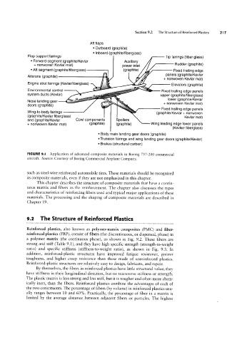
FIGURE 9.I Application of advanced composite materials in Boeing 757-200 commercial
aircraft. Source: Courtesy of Boeing Commercial Airplane Company.
such as steel-wire reinforced automobile tires. These materials should be recognized
as composite materials, even if they are not emphasized in this chapter.
This chapter describes the structure of composite materials that have a contin-
uous matrix and fibers as the reinforcement. The chapter also discusses the types
and characteristics of reinforcing fibers used and typical major applications of these
materials. The processing and the shaping of composite materials are described in
Chapter 19.
9.2 The Structure of Reinforced Plastics
Reinforced plastics, also known as polymer-matrix composites (PMC) and fiber-
reinforced plastics (FRP), consist of fibers (the discontinuous, or dispersed, phase) in
a polymer matrix (the continuous phase), as shown in Fig. 9.2. These fibers are
strong and stiff (Table 9.I), and they have high specific strength (strength-to-weight
ratio) and specific stiffness (stiffness-to-weight ratio), as shown in Fig. 9.3. In
addition, reinforced-plastic structures have improved fatigue resistance, greater
toughness, and higher creep resistance than those made of unreinforced plastics.
Reinforced-plastic structures are relatively easy to design, fabricate, and repair.
By themselves, the fibers in reinforced plastics have little structural value; they
have stiffness in their longitudinal direction, but no transverse stiffness or strength.
The plastic matrix is less strong and less stiff, but it is tougher and often more chem-
ically inert, than the fibers. Reinforced plastics combine the advantages of each of
the two constituents. The percentage of fibers (by volume) in reinforced plastics usu-
ally ranges between 10 and 60%. Practically, the percentage of fiber in a matrix is
limited by the average distance between adjacent fibers or particles. The highest