
Page 601 - 04. Subyek Engineering Materials - Manufacturing, Engineering and Technology SI 6th Edition - Serope Kalpakjian, Stephen Schmid (2009)
P. 601
582 Chapter 21 Fundamentals of Machining
different cutting operations. Note the considerable damage to the sur-
faces from BUE; its damage is manifested in the scuffing marks,
which deviate from the straight grooves that would result from nor-
mal machining, as seen in Fig. 21.2. Ceramic and diamond tools gen-
erally produce a better surface finish than other tools, largely because
Tool
of their much lower tendency to form a BUE.
A dull tool has a large radius along its edges, just as the tip of a
dull pencil or the cutting edge of a knife. Figure 21.22 illustrates the
relationship between the radius of the cutting edge and the depth of
cut in orthogonal cutting. Note that at small depths of cut, the rake
angle effectively can become negative and the tool simply may ride
over the workpiece surface instead of cutting it and producing chips.
This is a phenomenon similar to trying to scrape a thin layer from the
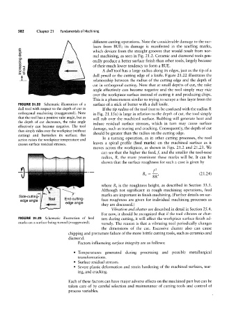
FIGURE 2l.22 Schematic illustration of a surface of a stick of butter with a dull knife.
dull tool with respect to the depth of cut in If the tip radius of the tool (not to be confused with the radius R
orthogonal machining (exaggerated). Note in Fig. 21.15 a) is large in relation to the depth of cut, the tool simply
that the tool has a positive rake angle, but as will rub over the machined surface. Rubbing will generate heat and
the depth of cut decreases, the rake angle induce residual surface stresses, which in turn may cause surface
effectively can become negative. The tool damage, such as tearing and cracking. Consequently, the depth of cut
then simply rides over the workpiece (without
should be greater than the radius on the cutting edge.
cutting) and burnishes its surface; this
In a turning operation, as in other cutting processes, the tool
action raises the workpiece temperature and
causes surface residual stresses. leaves a spiral profile (feed marks) on the machined surface as it
moves across the workpiece, as shown in Figs. 21.2 and 21.23. We
can see that the higher the feed, }Q and the smaller the tool-nose
radius, R, the more prominent these marks will be. It can be
shown that the surface roughness for such a case is given by
2
R, = %, (21.24)
where R, is the roughness height, as described in Section 33.3.
Although not significant in rough machining operations, feed
Side-cutting End;ming_ marks are important in finish machining. (Further details on sur-
face roughness are given for individual machining processes as
edge ang|e edge angle
they are discussed.)
Vibration and chatter are described in detail in Section 25.4.
For now, it should be recognized that if the tool vibrates or chat-
FIGURE 2I.23 Schematic illustration of feed ters during cutting, it will affect the workpiece surface finish ad-
marks on a surface being turned (exaggerated). versely. The reason is that a vibrating tool periodically changes
the dimensions of the cut. Excessive chatter also can cause
chipping and premature failure of the more brittle cutting tools, such as ceramics and
diamond.
Factors influencing surface integrity are as follows:
° Temperatures generated during processing and possible metallurgical
transformations.
° Surface residual stresses.
° Severe plastic deformation and strain hardening of the machined surfaces, tear-
ing, and cracking.
Each of these factors can have major adverse effects on the machined part but can be
taken care of by careful selection and maintenance of cutting tools and control of
process variables.
depth
singCfea
S