
Page 597 - 04. Subyek Engineering Materials - Manufacturing, Engineering and Technology SI 6th Edition - Serope Kalpakjian, Stephen Schmid (2009)
P. 597
578 Chapter 21 Fundamentals of Machining
EXAMPLE 21.3 Effect of Cutting Speed on Material Removal
The effect of cutting speed on the volume of metal and the tool travels 120 m/min >< 5 min = 600 m
removed between tool changes (or resharpenings) can before it has to be replaced.
be appreciated by analyzing Fig. 21.16. Assume that a Since the volume of material removed is
material is being machined in the “one” condition directly proportional to the distance the tool has
(that is, as cast with a hardness of 265 HB). We note traveled, it can be seen that by decreasing the cutting
that when the cutting speed is 60 m/min, tool life is speed, more material is removed between tool
about 40 min. Thus, the tool travels a distance of changes. It is important to note, however, that the
60 m/min >< 40 min = 2400 m before it has to be re~ lower the cutting speed, the longer is the time
placed. However, when the cutting speed is increased required to machine a part, which has a significant
to 120 m./min, the tool life is reduced to about 5 min economic impact on the operation (see Section 2S.8).
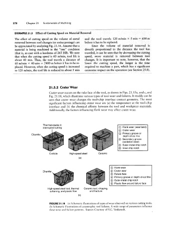
2l.5.2 Crater Wear
Crater u/ear occurs on the rake face of the tool, as shown in Figs. 21.15 a, and c, and
Fig. 21.18, which illustrates various types of tool wear and failures. lt readily can be
seen that crater wear changes the tool-chip interface contact geometry. The most
significant factors influencing crater wear are (a) the temperature at the tool-chip
interface and (bl the chemical affinity between the tool and workpiece materials.
Additionally, the factors influencing flank wear may affect crater wear.
Thermal cracks in
interrupted cutting ® Flank wear (wear land)
® Crater wear
Primary groove or
Chamfer C9
depth of cut line
Secondary groove
@
(oxidation wear)
© Outer-metal chip notch
@ Inner chip notch
Carbide High-speed steel Ceramic
(3)
G) Flank wear
Chamfer ® Crater wear
© Failure face
QD Primary groove or depth-of-cut line
® Outer-metal chip notch
© Plastic flow around failure face
High-speed steel tool, thermal Ceramic tool, chipping,
softening, and plastic flow and fracture
(bl
FIGURE 2 l.l8 (a) Schematic illustrations of types of wear observed on various cutting tools.
(b) Schematic illustrations of catastrophic tool failures. A wide range of parameters influence
these wear and failure patterns. Source: Courtesy of VC. Venkatesh.