
Page 598 - 04. Subyek Engineering Materials - Manufacturing, Engineering and Technology SI 6th Edition - Serope Kalpakjian, Stephen Schmid (2009)
P. 598
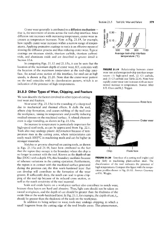
Crater wear generally is attributed to a diffusion mechanism-
that is, the movement of atoms across the tool-chip interface. Since 0.30
diffusion rate increases with increasing temperature, crater wear in-
co
creases as temperature increases. Note in Fig. 21.19, for example, E 0.15
how rapidly crater wear increases within a narrow range of temper-
atures. Applying protective coatings to tools is an effective means of
slowing the diffusion process and thus reducing crater wear. Typical
coatings are titanium nitride, titanium carbide, titanium carboni-
tride, and aluminum oxide and are described in greater detail in
Section 22.6.
In comparing Figs. 21.12 and 21.15a, it can be seen that the
location of the maximum depth of crater wear, KT, coincides with
FIGURE 2l.l9 Relationship between crater-
the location of the maximum temperature at the tool-chip inter-
wear rate and average tool-chip interface tempe-
face. An actual cross section of this interface, for steel cut at high
rature: (1) high-speed steel, (2) C1 carbide,
speeds, is shown in Fig. 21.20. Note that the crater-wear pattern
and (3) C5 carbide (see Table 22.4). Note how
on the tool coincides with its discoloration pattern, which is an
rapidly crater-wear rate increases with an incre-
indication of the presence of high temperatures. mental increase in temperature. Source: After
B.T. Chao and K.]. Trigger.
2 |.5.3 Other Types of Wear, Chipping, and Fracture
We now describe the factors involved in other types of cutting-
tool wear and fracture.
----l Rake face
Nose u/ear (Fig. 21.15a) is the rounding of a sharp tool
due to mechanical and thermal effects. It dulls the tool,
affects chip formation, and causes rubbing of the tool over
the workpiece, raising its temperature and possibly inducing
residual stresses on the machined surface. A related phenom-
enon is edge rounding, as shown in Fig. 21.15a. l Crater wear
An increase in temperature is particularly important for
high-speed steel tools, as can be appreciated from Fig. 22.1.
Tools also may undergo plastic deformation because of tem-
perature rises in the cutting zone, where temperatures can
easily reach 1000°C in machining steels and can be higher in
stronger materials.
Notc/Jes or grooz/es observed on cutting tools, as shown
in Figs. 21.15a and 21.18, have been attributed to the fact
that the region they occupy is the boundary where the chip is Chip Flank face
no longer in contact with the tool. Known as the depth-of-cut
line (DOC) with a depth VN, this boundary oscillates because FIGURE 2l.20 Interface of a cutting tool (right) and
of inherent variations in the cutting operation. Furthermore, chip (left) in machining plain-carbon steel. The
the region is in contact with the machined surface generated discoloration of the tool indicates the presence of
high temperatures. Compare this figure with the tempe-
during the previous cut; the thin work-hardened layer that
rature profiles shown in Fig. 21.12. Source: Courtesy
can develop will contribute to the formation of the wear
of P.K. Wright.
groove. If sufficiently deep, the notch can lead to gross chip-
ping of the tool tip because of its reduced cross section, as
well as the notch sensitivity of the tool material.
Scale and oxide layers on a workpiece surface also contribute to notch wear,
because these layers are hard and abrasive. Thus, light cuts should not be taken on
rusted workpieces, and the depth of cut should be greater than the thickness of the
oxide film or the work-hardened layer. In Fig. 21.3, for example, the depth of cut, to,
should be greater than the thickness of the scale on the workpiece.
In addition to being subject to wear, tools may undergo chipping, in which a
small fragment from the cutting edge of the tool breaks away. This phenomenon,
cn
rn
n
I-‘.
O
Crater-wearrate
D
/mn rn lv
>~
UI
O
3
I I
O1
5'O
‘es
2 O
CD
,B ed
“Der|S99 If
CDLQ
55”gm
\I .UH
O/ O
§O25
Carbide
Q)
-\
ERA DJ
-‘E :
Q. Os
f_°"U
CO
Carb;
'71 O05'
de E. O
95 E
-.
(B
3”
_L O
_.L
CD
O
O
UI
`|
O