
Page 594 - 04. Subyek Engineering Materials - Manufacturing, Engineering and Technology SI 6th Edition - Serope Kalpakjian, Stephen Schmid (2009)
P. 594
Section 21.5 Tool Life Wear and Fa|lure
2l.5.I Flank Wear
Flank wear occurs on the relief (flank) face of the tool (Figs. 21.15a, b, and e). It
generally is attributed to (a) rubbing of the tool along the machined surface, thereby
causing adhesive or abrasive wear (see Section 335) and (b) high temperatures,
which adversely affect tool-material properties.
In a classic study by F.\V Taylor on the machining of steels conducted in the
early 18905, the following approximate relationship for tool life, known as the
Taylor tool life equation, was established:
VT" = C. (21.20a)
Here, V is the cutting speed, T is the time (in minutes) that it takes to develop a
certain flank wear land (shown as VB in Fig. 21.15a), n is an exponent that de-
pends on tool and workpiece materials and cutting conditions, and C is a constant.
Each combination of workpiece and tool materials and each cutting condition
have their own 71 and C values, both of which are determined experimentally.
Generally, however, n depends on the tool material, as shown in Table 21.3, and C
on the workpiece material. Note that the magnitude of C is the cutting speed at
T - l H (21.20b)
T = 1 min.
To appreciate the importance of the exponent n, Eq. (21.20) can be rewritten as
C
,
where it can be seen that for constant values of C, the smaller the value of 11, the
lower is the tool life.
Cutting speed is the most important process variable associated with tool life,
followed by depth of cut and feed, For turning, Eq. (21.20) can be modified to
VT"d"f}' = C, (21.21)
where d is the depth of cut and f is the feed in mm/rev, as shown in Fig. 21.2. The ex-
T I C1/nv-1/nd-x/nf-y/na
ponents x and y must be determined experimentally for each cutting condition.
Taking n = 0.15, x = 0.15, and y = 0.6 as typical values encountered in machining
practice, it can be seen that cutting speed, feed rate, and depth of cut are of decreas-
ing importance.
We can rewrite Eq. (21.21) as
or, using typical values, as
T ~ C7V`7d`1f`4. (21.23)
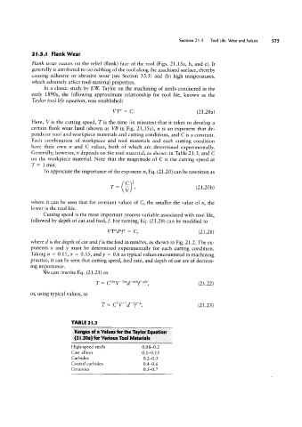
TABLE 2|.3
Ranges aff n Values for the Taylor Equation
(2l.20a) fur Various Tool Materials
High-speed steels 0.08-0.2
Cast alloys 0.1-0.15
Carbides 0.2-0.5
Coated carbides 0.4-0.6
Ceramics 0.5-0.7