
Page 180 - Marine Structural Design
P. 180
156 Part II Ultimate Strength
bracing members in semi-submersible drilling units have large D/t ratios, e.g. between 70 and
130. For such tubular members, local buckling may take place before or after the ultimate
strength is attained as Smith et al. (1979) and Bouwkamp (1975) observed in their
experiments. Therefore, the assessment of the load carrying capacity of such bracing members,
both ultimate strength and strength reduction due to local buckling, must be considered.
However, a systematic study of this phenomenon has not been performed yet.
In this chapter, a series of experiments are first carried out using large scale tubular test
specimens, which model a bracing member in an existing semi-submersible drilling unit. Axial
compressive loads are applied with eccentricity. Small-scale tubular test specimens are
prepared, of which D/t ratios are between 40 and 97, and tested under the same loading
conditions. Then, based on experimental results, an analytical model is proposed to simulate
the actual behavior of a tubular member considering the influence of local buckling.
Furthermore, the Idealized Structural Unit is developed by incorporating this model. The
validity and usefulness of the proposed model is demonstrated by comparing the calculated
results with the present and previous experimental results.
9.1.2 Safety Factors for Offshore Strength Assessment
The basic safety factors in offshore structural design are defined for two cases:
- Static loading: 1.67 for axial or bending stress. The static loads include operational gravity
loading and weight of the vessel.
- Combined static and environmental loads: 1.25 for axial or bending stress. The static loads
are combined with relevant environmental loads including acceleration and heeling forces.
For members under axial tension or bending, the allowable stress is the yield stress divided by
the factor of safety as defined in the above.
9.2 Experiments
9.2.1 Test Specimens
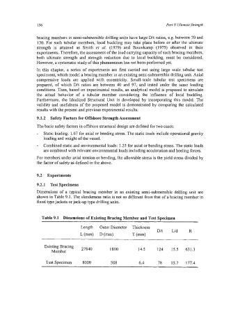
Dimensions of a typical bracing member in an existing semi-submersible drilling unit are
shown in Table 9.1. The slenderness ratio is not so different from that of a bracing member in
fixed type jackets or jack-up type drilling units.
Table 9.1 Dimensions of Existing Bracing Member and Test Specimen
Length Outer Diameter Thickness
D/t LJd R
Lt-1 D(m) T (mm)
Existing Bracing
Member 27840 1800 14.5 124 15.5 631.3
Test Specimen 8000 508 6.4 78 15.7 177.4