
Page 214 - Marine Structural Design
P. 214
190 Pari N Ultimate Strength
:
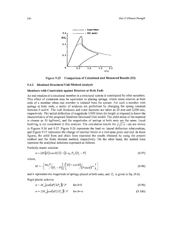
- Experlent
0.6 r ------- : COS -del
c/ cy
Figure 9.25 Comparison of Calculated and Measured Results (S3)
9.4.2 Idealized Structural Unit Method Analysis
Members with Constraints against Rotation at Both Ends
An end rotation of a structural member in a structural system is constrained by other members.
This effect of constraint may be equivalent to placing springs, which resist rotation at both
ends of a member when one member is isolated from the system. For such a member with
springs at both ends, a series of analyses are performed by changing the spring constant
between 0 and 00. The wall thickness and outer diameter are taken as 20 mm and 2,000 mm,
respectively. The initial deflection of magnitude MOO times the length is imposed to know the
characteristics of the proposed Idealized Structural Unit model. The yield stress of the material
is chosen as 30 kgf7mm2, and the magnitudes of springs at both ends are the same. Local
buckling is not considered in this analysis. The calculation results for r/m =loo are shown
in Figures 9.26 and 9.27. Figure 9.26 represents the load vs. lateral deflection relationships,
and Figure 9.27 represents the change of internal forces at a mid-span point and end. In these
figures, the solid lines and chain lines represent the results obtained by using the present
method and the finite element method, respectively. On the other hand, the dashed lines
represent the analytical solutions expressed as follows:
Perfectly elastic solution
w= 2M[l/(2cosW/2)-1]+a0 P,/(P, -P) (9.97)
where,
(9.98)
and k represents the magnitude of springs placed at both ends, and PE is given in Eq. (9.6).
Rigid plastic solution
w = M, [co~(~P/~P,)]/P for &O (9.99)
w = 2kt,[cos(n~/~~,)l/~ for kco (9.100)