
Page 226 - Marine Structural Design
P. 226
202 Pari II Ultimate Strength
In Figure 10.3, the buckling coefficient c has been plotted against the aspect ratio for a simply
supported plate subjected to uniform compression. It appears that the minimum buckling stress
occurs when the length is a multiple of the width. For intermediate values, the number of
waves is incompatible with the plate's length, hence raising the buckling load. In practice,
however, this additional strength is not taken into account.
10.1.3 Boundary Conditions
The actual boundary conditions will differ from the idealized cases. The major influence stems
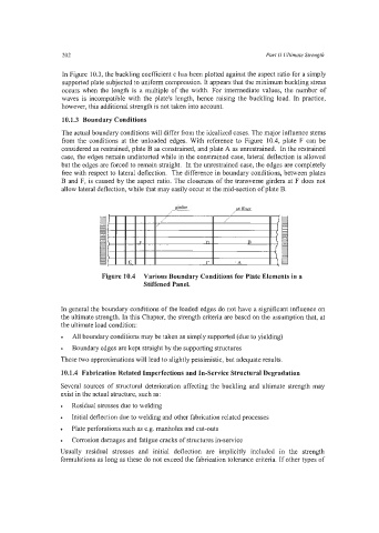
from the conditions at the unloaded edges. With reference to Figure 10.4, plate F can be
considered as restrained, plate B as constrained, and plate A as unrestrained. In the restrained
case, the edges remain undistorted while in the constrained case, lateral deflection is allowed
but the edges are forced to remain straight. In the unrestrained case, the edges are completely
free with respect to lateral deflection. The difference in boundary conditions, between plates
B and F, is caused by the aspect ratio. The closeness of the transverse girders at F does not
allow lateral deflection, while that may easily occur at the mid-section of plate B.
Figure 10.4 Various Boundary Conditions for Plate Elements in a
Stiffened Panel.
In general the boundary conditions of the loaded edges do not have a significant influence on
the ultimate strength. In this Chapter, the strength criteria are based on the assumption that, at
the ultimate load condition:
All boundary conditions may be taken as simply supported (due to yielding)
Boundary edges are kept straight by the supporting structures
These two approximations will lead to slightly pessimistic, but adequate results.
10.1.4 Fabrication Related Imperfections and In-Service Structural Degradation
Several sources of structural deterioration affecting the buckling and ultimate strength may
exist in the actual structure, such as:
Residual stresses due to welding
Initial deflection due to welding and other fabrication related processes
Plate perforations such as e.g. manholes and cut-outs
Corrosion damages and fatigue cracks of structures in-service
Usually residual stresses and initial deflection are implicitly included in the strength
formulations as long as these do not exceed the fabrication tolerance criteria. If other types of