
Page 277 - Marine Structural Design
P. 277
Chapter I3 Collapse Analysis of Ship Hulls 253
adopted for large displacement analyses. Arbitrarily large rotations but small strains are
assumed. Using the virtual work principle, we obtain @ai & Pedersen, 1991):
[khlbel= (d.1 (13.1)
where,
LkE I= IkL 1' LkG 1' LkD 1 (13.2)
and where fd:] and {&> are the increments of the elastic nodal displacements and nodal
forces. The elastic stiffness matrix [KE] is composed of a linear stiffness matrix [KL], a
geometric stiffness matrix [KG], and a deformation stiffness matrix [K,]. The deformation
stiffness matrix [K,], makes it possible to model a beam-column member using a minimum
number of elements, since it accounts for the coupling between axial and lateral deformations.
The elastic-plastic stiffness matrix [Kp] is obtained by applying the plastic node method
(Ueda & Yao, 1982):
[k,l{duf = w (13.3)
(13.4)
(13.5)
0
and where (du) denotes the increment of nodal displacements
{0} for elastic node
{
{Oil={ ac /axi} for plastic node (i = 1,2) (13.6)
where r]. is a fully plastic yield function and {xi}denotes the nodal forces at node Y'.
I X
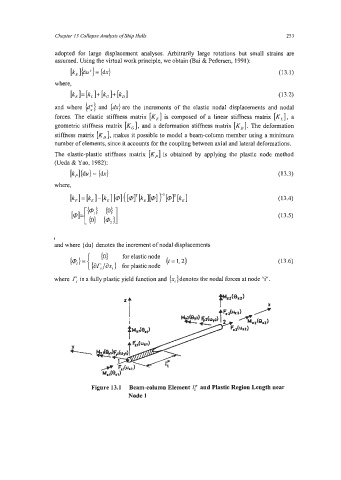
Figure 13.1 Beam-column Element I! and Plastic Region Length near
Node 1